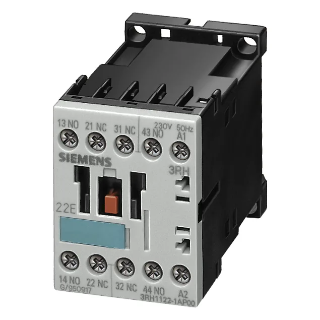
Siemens 3RT1517-2GG20-ZX95 — Contactors

Siemens 3RT1517-2GG20-ZX95 SIRIUS Contactor, Size S00, 24 VD

MPN3RT1517-2GG20-ZX95

Siemens SIRIUS 3RT1517-2GG20-ZX95 power contactor, Size S00, 24 VDC coil, 10 A rated current, spring-loaded terminals for main and control circuits, screw and snap-on mounting on 35 mm DIN rail.

Sourced new & surplus through independent channelsAuthenticity-screened · ESD-safe packingListing updated Jul 2026

Specifications

3RT1517-2GG20-ZX95 — Identification
ParameterValue
Contactor frame sizeS00
3RT1517-2GG20-ZX95 — Ratings & Performance
ParameterValue
Rated operational current, AC-12, max.10 A
Rated value @ 400 V3 A
Rated value @ 230 V6 A
Rated value @ 24 V10 A
Rated value @ 60 V2 A
Rated value @ 110 V1 A
Rated value @ 220 V0.3 A
3RT1517-2GG20-ZX95 — Control & Coil
ParameterValue
Control supply voltage typeAC
Rated value @ 50 Hz3.8 V·A
Rated value @ 50 Hz110 V
3RT1517-2GG20-ZX95 — Contacts & Poles
ParameterValue
Main poles4
Main NO contacts2
Auxiliary contact reliability1 faulty switching per 100 million (17 V, 1 mA)
3RT1517-2GG20-ZX95 — Protection & Coordination
ParameterValue
Short-circuit coordination type 1, fusefuse gL/gG: 35 A
Short-circuit coordination type 2, fusefuse gL/gG: 20 A
Aux. switch short-circuit protection, fusefuse gL/gG: 10 A
3RT1517-2GG20-ZX95 — Connection & Mounting
ParameterValue
Main circuit connectionspring-loaded terminals
Aux. / control circuit connectionspring-loaded terminals
Conductor cross-section, solid2x (0.25 ... 2.5 mm²)
Conductor cross-section, solid or stranded2x (0,25 ... 2,5 mm²)
Conductor cross-section, finely stranded w/ ferrule2x (0.25 ... 1.5 mm²)
Mounting methodscrew and snap-on mounting onto 35 mm standard mounting rail according to DIN EN 50022
Side-by-side mountingYes
3RT1517-2GG20-ZX95 — Durability
ParameterValue
Durability (operating cycles, typ.)10 000 000
Durability with aux. switch block (cycles, typ.)10 000 000
3RT1517-2GG20-ZX95 — Environmental
ParameterValue
Installation altitude, max.2 000 m
3RT1517-2GG20-ZX95 — Mechanical
ParameterValue
Width45 mm
Height60 mm
Depth72 mm
3RT1517-2GG20-ZX95 — Specifications
ParameterValue
At AC4 ... 30 ms

Product details

Rated impulse withstand voltage is 6 kV for both the main circuit and the auxiliary circuit, placing it in a standard overvoltage category for industrial environments. The coil draws 3.8 VA at 50 Hz and holds at 24 VDC nominal.

For motor duty, the contactor is coordinated with a fuse gL/gG 20 A under type 2 assignment — meaning a short-circuit fault up to that fuse rating will not damage the contactor, only the fuse needs replacement. This coordination is critical for panel builders who need to guarantee fault withstand without contactor replacement. Auxiliary contacts are rated 12 A per NC and per NO contact at the rated value, with a 20 A peak at 24 V for both NC and NO. Terminals accept solid or stranded conductors 2x (0.25 to 2.5 mm²) or AWG 2x (24 to 14). The spring-loaded design reduces installation time compared to screw terminals and provides vibration-resistant connections — a practical advantage in panels subject to transport or machine vibration.

Side-by-side mounting is permitted, which allows dense packing in multi-contactor panels. These values matter when coordinating with upstream protection devices or sequencing contactors in star-delta or reversing starters.

RoHS compliance is documented with a substance prohibition date of 01 July 2006, confirming the part meets EU RoHS requirements. Storage temperature range of -55 to +80 °C covers most warehouse and transport conditions.

Frequently asked questions

What wire sizes does the spring-loaded terminal accept?

Solid or stranded conductors: 2x (0.25 to 2.5 mm²) or AWG 2x (24 to 14).

MPN
3RT1517-2GG20-ZX95