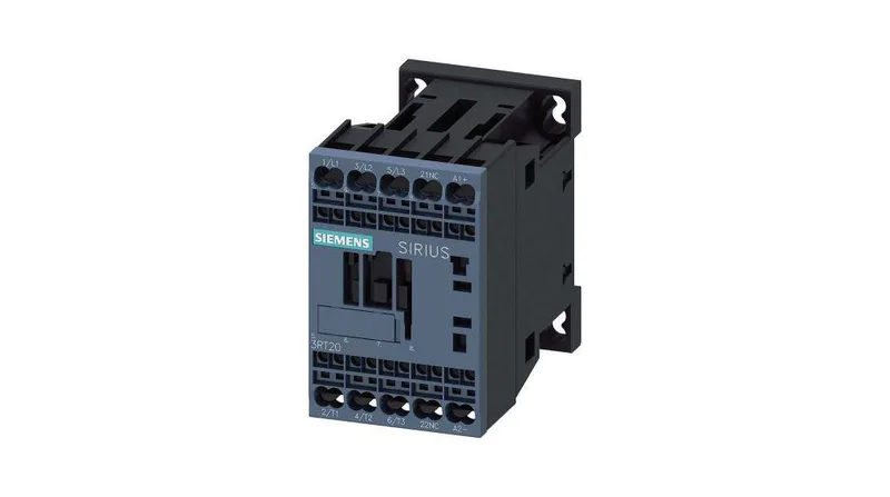
What it is and where it fits
The 3RT2015-2KB42: The 24 V DC coil draws its rated value and the contactor breaks up to 10 A at 24 V DC (DC-13 duty), which covers most PLC output and relay interface loads. For motor loads, it is rated 0.75 hp at 230 V. Mounting is screw or snap-on onto 35 mm DIN rail per DIN EN 60715, with a 45 mm width that fits standard panel layouts. The mounting position allows +/-180° rotation and +/-22.5° tilt on a vertical surface, giving flexibility in tight enclosures.
Key ratings and what they mean for your panel
The DC-13 breaking current table tells you exactly what inductive DC load this contactor can interrupt: 10 A at 24 V, 2 A at 48 V and 60 V, 1 A at 110 V, 0.9 A at 125 V, 0.3 A at 220 V, and 3 A at 400 V. These are the numbers that govern fit for solenoid valves, DC brake coils, and DC motor contactors — not the AC ratings. Mechanical endurance is 30 million operations typical, so this contactor is built for high-cycle applications like packaging lines or machine tool turrets. The maximum switching rate varies by duty: 1000 cycles/h for AC-1 resistive, 750 cycles/h for AC-2 and AC-3 motor starting, and 250 cycles/h for AC-4 inching/plugging. Operating temperature range is -25 to +60 °C, with storage from -55 to +80 °C. That covers most industrial enclosures without derating, but if the panel sits near a furnace or in a desert cabinet, the +60 °C operating limit is the one to watch.
Termination and wiring
The magnet coil uses spring-type terminals — no screwdriver needed for the coil connection, which speeds up panel wiring. Main contacts accept solid or stranded conductors from 0.5 to 4 mm², and the terminals can take two conductors per clamp (2x 0.5-4 mm²), useful for daisy-chaining control power. This contactor has no built-in auxiliary switch block. If you need N/O or N/C feedback for the PLC, you will add a separate SIRIUS auxiliary contact block that clips onto the front. The 3RT2015 frame has the standard slot for that.
Clearance and panel layout
Minimum clearances to adjacent components: 10 mm upwards, 10 mm downwards, 10 mm forwards, and 6 mm at the side. The 73 mm depth includes the coil terminals, so account for that when routing wires behind the DIN rail. Overall dimensions are 45 mm wide, 70 mm tall, and 73 mm deep — a compact footprint that leaves room for additional contactors or terminal blocks in the same row.