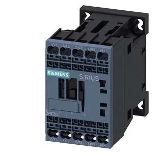
Size S00 power contactor, spring terminals, 24 VDC coil
The Siemens 3RT2016-2FB41 is a SIRIUS power contactor in the compact S00 frame — 45 mm wide, 73 mm deep, 70 mm tall — with a 24 VDC magnet coil terminated via spring-type terminals. That spring cage on the coil means no screwdriver torque check; strip the wire to the right length and push it home. Rated DC-1 switching at 24 V is 10 A, dropping to 3 A at 400 VDC, so it covers DC motor brakes, solenoid valves, and small DC bus isolation in control panels. Snap it onto 35 mm DIN rail per EN 60715 or screw-mount it — the mounting position allows ±180° rotation on a vertical surface plus ±22.5° tilt forward/backward. That flexibility matters when you're shoehorning a contactor into a tight gland-plate area or a retrofit panel where the original backplate holes don't align.
DC switching performance and auxiliary contacts
The DC switching curve on this S00 contactor is not linear: 10 A at 24 V, 2 A at 48 V and 60 V, 1 A at 110 V, 0.9 A at 125 V, 0.3 A at 220 V. That's the DC-1 resistive load curve — inductive DC loads (brake coils, DC motor armatures) need derating below these numbers. The arcing time runs 10 to 15 ms, with a dropout delay of 38 to 65 ms after coil removal, which gives the safety circuit time to sequence downstream contactors. An auxiliary switch is built in — 1 N/O + 1 N/C on the main contact block, rated for 20 to 12 V? The evidence shows 'For Main Contacts 20... 12' which likely indicates the auxiliary contact rating range, though the unit is unclear. The contactor itself is rated for 30 million mechanical operations typical, so it outlasts most panel cycles.
If you're looking at a panel originally built around the 3RT2016-1AG62 (a similar S00 contactor with screw terminals and a different coil voltage), the 2FB41 will drop into the same DIN-rail footprint and mounting hole pattern — same 45 mm width, same S00 frame. The swap is a terminal-style change, not a panel rework.
Wiring and panel integration
Spring-type terminals on both coil and main contacts accept 0.5 to 4 mm² solid or stranded wire, or 2x (0.5 to 4 mm²) in parallel. Clearance: 10 mm upward, 10 mm forward, 10 mm downward, 6 mm to the side — tight enough for a crowded DIN rail but leave the side gap for heat dissipation at high switching rates (750 ops/hour at AC-3). The contactor can handle the thermal cycling of a non-climate-controlled enclosure, but the coil hold-in voltage is 0.8 x nominal (19.2 VDC) and the full-scale dropout is 1.1 x nominal (26.4 VDC) — so if your 24 VDC supply sags below 19 V during a motor start, the contactor drops out.