What It Is and What It Does
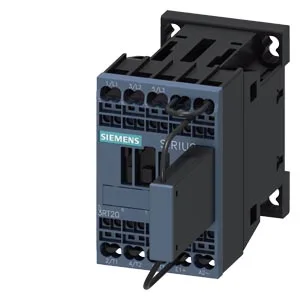
The Siemens SIRIUS 3RT2017-2KB42-1LA0 is a Size S00 contactor with a 24 VDC coil, designed for switching motor and resistive loads in control panels. It is part of the SIRIUS family, a broad platform for industrial switching and protection. The coil termination uses spring-type terminals, which means no screwdriver is needed for the control wiring — a time-saver during panel build and a reliable connection that won't loosen under vibration. The contactor mounts on a 35 mm DIN rail per DIN EN 60715, either snapped on or screwed, and is rated for standing operation on a horizontal surface. This is the standard mounting for panel builders; the 45 mm width fits a single modular device pitch.
Key Ratings and What They Mean for Your Circuit
For DC switching, the contactor is rated 10 A at 24 V, 2 A at 48 V and 60 V, 1 A at 110 V, 0.9 A at 125 V, 3 A at 400 V, and 2 A at 500 V and 690 V. These are the make-and-break capacities for DC loads — the current drops as voltage rises because DC arcs are harder to extinguish. The 10 A at 24 VDC is the figure that matters for most control-circuit or small DC-motor applications. For AC loads, the contactor is rated 11 A at 480 V and 600 V, and 2 hp at 230 V. The 11 A at 480 V is the general-purpose rating for three-phase motor switching in North American 480 V panels; the 2 hp at 230 V covers single-phase motor duty. Mechanical life is rated at 30,000,000 operations typical — this is the expected lifespan before mechanical wear, not electrical endurance under load. Electrical life depends on the load type and switching frequency; for high-cycle applications like conveyors, derate accordingly. Operating temperature range is -40 to +70 °C, with storage from -55 to +80 °C. This covers most indoor panel environments, including unheated enclosures in cold climates.
Panel Integration and Wiring
Dimensions are 45 mm wide, 70 mm high, and 121 mm deep. The 45 mm width is the standard single-module pitch for DIN-rail components, so it occupies one slot in a typical panel layout. Required clearances: 10 mm upwards, 10 mm forwards, 10 mm downwards, and 6 mm at the sides. These are the minimum air gaps needed for heat dissipation and arc flash — crowding the contactor against other devices or the enclosure wall will shorten its life. Main contact wiring accepts solid or stranded conductors: 2x (0.5 to 1.5 mm²), 2x (0.75 to 2.5 mm²), or 2x 4 mm². The spring terminals grip the wire without needing ferrules, though ferruled stranded wire is still recommended for repeated re-termination. The contactor includes an auxiliary switch, which can be used for status feedback to a PLC or for electrical interlocking in reversing or star-delta starters.