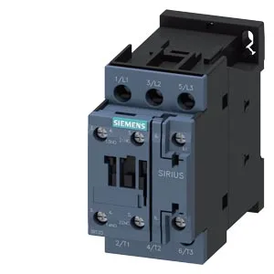
SIRIUS S0 Power Contactor – What You're Getting
Mounting is screw-and-snap-on onto 35 mm DIN rail per DIN EN 60715, and the mounting position allows +/-180° rotation on a vertical surface plus +/-22.5° forward/backward tilt — useful when you're squeezing it into a tight enclosure corner. The mechanical life is listed at 10 million typical cycles — that's the contactor body itself, not the contacts under load.
The auxiliary contact ratings tell you what the built-in switch can handle at different control voltages: 10 A at 24 V, 2 A at 48 V, 2 A at 60 V, 1 A at 110 V, 0.9 A at 125 V, 0.3 A at 220 V, and 3 A at 400 V. At 440 V it drops to 0.6 A. These are the limits for the auxiliary circuit — don't push more through the built-in switch than these numbers allow. Switching frequency varies by duty class: 1,000 cycles/hour at AC-1 (resistive loads), 750 cycles/hour at AC-2 and AC-3 (motor starting/running), and 250 cycles/hour at AC-4 (plugging, inching). The AC-3e rating matches the AC-3 figure at 750 cycles/hour. The auxiliary circuit wiring uses 2x (0.5 to 1.5 mm²) or 2x (0.75 to 2.5 mm²) solid or stranded. Arcing time is 10 to 10 ms — a tight window, meaning the arc extinguishes fast, which helps contact life.
Clearance and Panel Fit
That depth is the dimension from the DIN rail mounting surface to the furthest point of the contactor body — critical when you're calculating enclosure depth with the door closed. These are the minimum air gaps for heat dissipation and arc containment — don't crowd it tighter. Coil consumption is 0.25 VA at 50 Hz and 0.28 VA at 60 Hz — low enough that a standard 24 VDC power supply can drive it without a separate coil driver, but verify the inrush if you're paralleling multiple contactors on one supply.