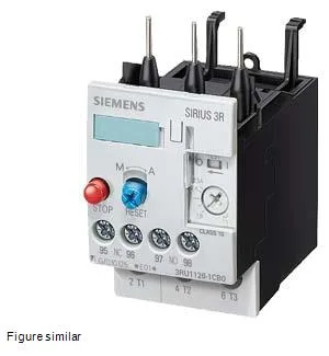
Thermal overload relay for motor protection
Main and auxiliary circuits use screw-type terminals; the main circuit accepts 2x (0.5... 1.5 mm²) solid or 2x (0.75... 2.5 mm²) finely stranded with ferrule, and the auxiliary circuit uses the same range — matching common panel wiring practice for motor starters up to the S0 frame.
Mounts directly onto a contactor (contactor mounting, per) — no DIN-rail adapter needed. The S0 footprint is 45 mm wide, 97 mm tall, 96 mm deep, with zero clearance required upwards, forwards, and backwards, and 6 mm at the side.
Auxiliary contact ratings and power dissipation
Auxiliary contact ratings: 1 A at 24 V, 0.22 A at 110/125 V, 2 A at 230 V, 1 A at 400 V, plus 3 A at 120 V and 0.11 A at 220 V — these cover control-circuit loads across common AC and DC control voltages. Power dissipation per pole is 2.7 W, so three poles add 8.1 W of heat inside the enclosure; account for that in the thermal budget.
Operating temperature range -20 to +70 °C, storage/transport -55 to +80 °C, 100 % relative humidity during operation. Shock resistance 8g for 10 ms, surge voltage withstand 6 kV. ATEX approval DMT 98 ATEX G 001 for explosive-gas environments. Substance prohibition date 07/01/2006 — RoHS-compliant since then.