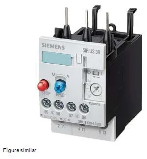
It mounts directly to a contactor — the fastening method is contactor mounting — and uses a bimetallic strip to model motor heating, tripping the auxiliary contacts when the thermal model exceeds the set point.
Both the main current circuit and the auxiliary/control circuit use screw-type terminals. The main circuit accepts solid conductors 2x (0.5... 1.5 mm²) and 2x (0.75... 2.5 mm²), or AWG 2x (16... 12) and 2x (14... 8). The auxiliary contacts accept 2x (0.5... 1.5 mm²) and 2x (0.75... 2.5 mm²) finely stranded with core end processing, or AWG 2x (20... 16) and 2x (18... 14). The auxiliary contact ratings are given at multiple voltages: 1 A at 24 V, 3 A at 120 V, 2 A at 230 V, and 1 A at 400 V — these are the switching capacities for the built-in N/C and N/O contacts that signal the trip to the control circuit.
Mechanical integration
The power dissipation per pole is 2.7 W — for a 3-pole relay at full load, that is 8.1 W of heat to remove from the enclosure.