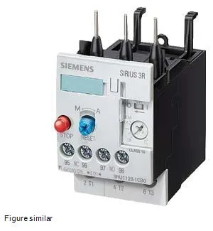
Its CLASS 10 trip class means it will trip within 10 seconds at 7.2× the set current, which is the standard for protecting standard induction motors during start-up — a mismatch here (specifying CLASS 20 for a fast-starting pump, for example) risks nuisance tripping or inadequate protection.
This relay mounts directly onto a contactor via the fastening method (contactor mounting), so no separate DIN-rail footprint is consumed — it stacks on the contactor's top. The S0 frame size mates with S0 contactors in the SIRUS range. The mounting position allows rotation of ±135° on a vertical surface and tilting of ±45° forward/backward, which gives panel builders flexibility for cable entry orientation.
Termination and wiring constraints
Main circuit terminals accept solid conductors of 2× (0.5…1.5 mm²) and 2× (0.75…2.5 mm²), or the AWG equivalents 2× (16…12) and 2× (14…8). Auxiliary and control circuit terminals accept 2× (20…16) and 2× (18…14) AWG. Finely stranded conductors with end processing follow the same cross-section ranges. These are standard panel-building sizes, but verify that your motor leads are within these ranges — a 4 mm² motor cable will not fit without a ferrule reduction or terminal adapter. The per-pole power dissipation is 2.7 W, which matters for thermal management inside a sealed enclosure with multiple relays stacked.