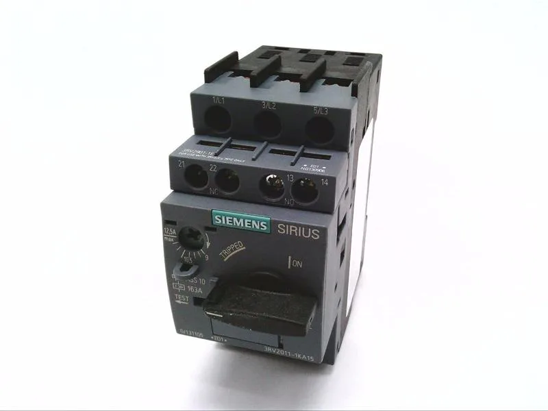
Motor protection circuit breaker — SIRIUS 3RV2011-1KA15
The Class 10 trip characteristic (Trip Class CLASS 10) matches standard NEMA and IEC motor heating curves, so it protects the motor winding during a stalled-rotor condition without nuisance tripping on a normal start.
Mounting and integration — DIN rail, 45 mm wide
At 45 mm wide (Width 45 mm) and 97 mm deep (Depth 97 mm), it occupies a single modular space — fits neatly into a motor control center (MCC) bucket or a standalone panel enclosure. Clearance requirements: 50 mm upward and downward, 30 mm at the sides. Forwards and backwards clearance is zero — it can sit flush against the backplane or a neighboring device. That 50 mm vertical gap is the one to watch when stacking multiple breakers in a row; the arc-chute exhaust needs that space. Terminals for main contacts accept 2x (0.5 to 1.5 mm²) or 2x (0.75 to 2.5 mm²) solid or stranded copper — screw terminals (M3). That covers the typical motor feed from a 1.5 mm² control cable up to a 2.5 mm² power cable for a small motor branch.
Back-up fuse coordination — what the ratings mean
When the prospective fault current exceeds the breaker's interrupting rating, the manufacturer specifies back-up fuse limits: gL/gG 63 A at 400 V, gL/gG 50 A at 500 V, and gL/gG 40 A at 690 V. These are the maximum fuse ratings that, in series, allow the breaker to safely clear a fault without the fuse needing to blow first. If your panel has a 100 A upstream fuse at 400 V, you need a different breaker or a current-limiting fuse ahead of this one. The auxiliary contact ratings cover the control circuit: 1 A at 24 V, 0.5 A at 120/125/230 V, and 0.15 A at 60 V.
Operating conditions and switching frequency
Rated for 15 switching operations per hour maximum under AC-3 and AC-3e duty — that's the standard motor-switching category (starting and stopping a squirrel-cage motor). If your application cycles more frequently (e.g., jogging or inching), you'll need to derate or move to a contactor-based solution with a separate overload relay.