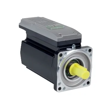
Where does a 3.5 N·m integrated-drive servo fit the PacDrive 3 line?
The ILM1003P12A0000: The part is a servo motor integrated drive in the PacDrive 3 range, device short name ILM, sized for the 1100 W / 3.5 N·m continuous nominal point at 3000 rpm — that envelope sits in the lower-mid of the ILM family and is typically dropped into a packaging-machine axis, a small pick-and-place, or a labelling station where the drive electronics are mounted on the motor back to cut cabinet space and wiring.
Torque envelope — what 3.5 / 28.3 N·m means on the bench
Nominal torque is 31.0 lbf.in (3.5 N·m) with a continuous stall torque of 51.3 lbf.in (5.8 N·m), and the peak stall reaches 250.5 lbf.in (28.3 N·m) — roughly 8× nominal — so the motor absorbs acceleration bursts (indexing, clamp-and-cut moves) without oversizing the continuous rating; the torque constant of 1.61 N·m/A at 248 °F (120 °C) is what the drive uses to close the current loop. Maximum current Irms is 21.2 A against a line-rated 2.4 A and a continuous stall current of 3.6 A, so the inverter section must be rated for the Irms peak even though the thermal design point is the 3.6 A continuous figure — sizing the upstream DC bus and brake resistor to the peak, not the nominal, is what keeps fast stops from tripping DC-bus overvoltage.
Shaft, feedback, and the options this build skips
Mechanical envelope: 11.2 in (285 mm) length, 3.9 in (100 mm) flange, keyed shaft of 0.7 in (19 mm) × 1.6 in (40 mm), no second shaft end, no holding brake, 4 mounting holes on a 9 mm bolt circle with a 3.7 in (95 mm) centring collar set 0.1 in (3.5 mm) deep — this is the brake-less, single-shaft build used where an external brake or a back-up encoder is not required. Feedback is absolute multiturn SinCos Hiperface with 128 periods of speed feedback resolution, so position is retained across power cycles without a battery box — the drive reads absolute position on first enable, then closes the velocity loop on the SinCos signal at runtime.
Mechanical load limits and what they do to machine sizing
Maximum radial force Fr derates from 1050 N at 1000 rpm to 830 N at 2000 rpm and 730 N at 3000 rpm, and the maximum axial force Fa is 0.2 × Fr — these are the bearing-life limits the mechanical designer has to check against belt tension or pinion forces, not the drive’s electrical envelope; radial load drives bearing life, not motor heating. Stator resistance 2.6 Ohm Ph/Ph at 68 °F (20 °C) and inductance 15.6 mH Ph/Ph at the same point (7.8 mH Ph/N at 248 °F / 120 °C) are the constants the drive firmware uses to tune the current loop — the 20 °C / 120 °C split is what the controller uses to compensate for copper shifts as the motor warms into its rated operating band.