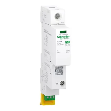
Schneider Electric A9L8F451 — Surge Protection Devices (SPD)

Schneider Electric A9L8F451 Acti9 iPRD Type 2+3 Surge Arrest

MPNA9L8F451
Active

Schneider Electric Acti9 iPRD, Type 2+3 surge arrester, 1P+N, 230/240 V AC, 20 kA nominal discharge current (L/N), 25 kA short-circuit withstand, plug-on mounting, white (RAL 9003).

Sourced new & surplus through independent channelsAuthenticity-screened · ESD-safe packingListing updated Aug 2026

Specifications

A9L8F451 — Identification
ParameterValue
Product nameActi9 iPRD
Product/component typeSurge arrester with pluggable cartridge
Product rangeActi9
Device applicationDistribution
A9L8F451 — Protection ratings
ParameterValue
SPD class/typeType 2 + 3
Max. continuous operating voltage (Uc)Differential mode: 340 V L/N Common mode: 305 V N/PE
Voltage protection level (Up)Differential mode Common mode <1.5 kV N/PE
Nominal discharge current (In)Differential mode: 20 kA (L/N) Common mode: 40 kA (N/PE)
Max. discharge current (Imax)Differential mode: 40 kA L/N Common mode: 65 kA N/PE
Surge arrester technologyMOV + GDT
Surge arrester typeElectrical distribution network
Response time< 25 ns L/N < 100 ns N/PE
Open-circuit voltage (Uoc)6000 V differential mode L/N 6000 V common mode N/PE
Follow current (Ifi)100 A common mode N/PE
A9L8F451 — Electrical
ParameterValue
Rated operational voltage (Ue)230/240 V AC at 50/60 Hz
Pole configuration1P + N
Earthing systemTT TN-S TN-C-S
A9L8F451 — Signalling
ParameterValue
Local signallingOperating state: flag (green) Fault indication: flag (red)
Remote signallingWith
Signalling circuit rating1 A/250 V AC 1 A/125 V AC 0.5 A/48 V DC 0.5 A/24 V DC 0.5 A/12 V DC 0.01 A/5 V DC
A9L8F451 — Approvals
ParameterValue
StandardsIEC 61643-11:2011 BS EN 61643-11:2012+A11:2018
Quality labels / certificationsUKCA
A9L8F451 — Environmental
ParameterValue
Operating ambient temperature-40...85 °C
Relative humidity5...95 %
Ingress protection (IP)IP20 with device wired
Impact protection (IK)IK05
Operating altitude0...2000 m
A9L8F451 — Mechanical
ParameterValue
Mounting modePlug-on (chassis)
Width18 mm
Height129 mm
Depth85 mm
9 mm pitch units2
Terminal tightening torqueRemote control: 0.2...0.25 N.m Power terminals: 3.5 N.m Earthing terminal: 2 N.m
ColourWhite (RAL 9003)
MaterialThermoplastic

Product details

It covers a single phase (1P+N) at 230/240 V AC, 50/60 Hz. The 20 kA nominal discharge current per differential mode (L/N) and 40 kA common mode (N/PE) mean it handles direct lightning-induced surges on a service entrance or sub-distribution board, not just switching transients. The 25 kA short-circuit withstand ensures the device clears a fault without rupturing upstream — critical for coordination in a panel where the main breaker is sized above that level.

The Type 2 + 3 classification tells you this arrester handles both main incoming surges (Type 2 at the sub-distribution board) and equipment-level protection (Type 3 close to the load) in one unit — no need for a separate fine-protection stage downstream. The MOV + GDT technology combines a metal-oxide varistor for clamping with a gas discharge tube for follow-current extinction; the GDT handles the 100 A common-mode follow current that would otherwise stress a MOV alone. Response time under 25 ns on L/N and under 100 ns on N/PE means it catches fast-rising transients — the kind that damage switch-mode power supplies and electronics before a slower arrester reacts. Temporary overvoltage (TOV) withstand is a real differentiator: 337 V L/N for 5 seconds before failure, and 442 V L/N for 120 minutes in safe failure mode. That means the arrester survives a neutral shift or back-feed from a generator long enough for protection to clear, rather than venting immediately. The N/PE path handles 1200 V for 200 ms — a direct lightning strike to the PEN conductor. If you are specifying for a site with weak utility regulation or generator backup, this TOV curve is the spec that keeps the arrester from becoming the failure point. The pluggable cartridge lets you replace the MOV/GDT module without rewiring the base — a maintenance spare you can swap in under a minute while the board stays live upstream. Local signalling uses a green flag for operating state and red for fault; remote signalling contacts rated 1 A/250 V AC allow a PLC or building management system to log the failure.

Tested to IEC 61643-11:2011 and BS EN 61643-11:2012+A11:2018. UKCA marked for the UK market.

Frequently asked questions

What is the nominal discharge current of A9L8F451?

The nominal discharge current is 20 kA differential mode (L/N) and 40 kA common mode (N/PE). Maximum discharge current is 40 kA L/N and 65 kA N/PE.

What earthing systems does A9L8F451 support?

It supports TT, TN-S, and TN-C-S earthing systems, which covers the vast majority of UK and European distribution installations.

What compliance documentation does Schneider provide for A9L8F451?

The device is tested to IEC 61643-11:2011 and BS EN 61643-11:2012+A11:2018, and carries UKCA marking. Standard Schneider documentation includes a declaration of conformity and test reports per those standards.

MPN
A9L8F451