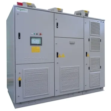
Physical footprint and site integration
The ATV1200A10003333: This Altivar 1200 drive ships in a floor-standing enclosure with separate air flows for the power cells and transformer — not a cabinet you retrofit into an existing panel. Standard-efficiency configuration measures 3560 mm wide by 1400 mm deep by 2670 mm high; the high-efficiency variant adds width to 3860 mm and depth to 1500 mm while keeping the same 2670 mm height. The cooling system moves 13,200 m³/h in standard efficiency and 19,800 m³/h in high efficiency — that volume has to be ducted or room-conditioned, not just vented. Noise output is 80 dB, which places this drive in a separate electrical room or a dedicated enclosure area, not on a production floor near operators.
Power stage and input topology
Rated for 836 kW motor power at 1000 kVA apparent power, with a supply voltage window of 2970 to 3630 V. The input stage is an 18-pulse diode rectifier bridge — that topology cancels the 5th and 7th harmonics at the transformer secondary, so the drive meets IEEE 519 without a separate active filter on most utility feeds. Output voltage tracks the supply voltage (no buck/boost), so the motor sees whatever the incoming line delivers under load. Prospective short-circuit withstand is 31.5 kA for 150 ms — the upstream protection must coordinate to clear within that window or the drive's internal bracing becomes the weak link.
Overload capability and duty cycle
Two overload profiles are available. Standard overload handles 1.2× rated current for 60 seconds and 1.5× for 3 seconds. High overload pushes to 1.5× for 60 seconds and 1.85× for 3 seconds. The high-overload setting is the one to specify if the driven load has intermittent peak torque demands — a crusher, a centrifuge, or a loaded conveyor start.
Control complement and isolation
Six discrete inputs standard (expandable to ten) and four analogue inputs, all software-configurable for 0–20 mA or 4–20 mA. Two analogue outputs follow the same current-loop range. Electrical isolation between power and control is maintained, so the 24 V DC control circuits stay referenced to ground even when the 3 kV power stage faults. The control supply requires an external 220 V AC source at 3 kVA — it does not derive from the DC bus. The cooling fan has its own internal 380 V AC supply, with an optional external 380 V AC feed for redundancy. This separation means the control electronics stay alive during a DC-bus discharge cycle.
CE marked, designed to EN/IEC 61800-3 (EMC environment), EN/IEC 61800-4 (harmonics), EN/IEC 61800-5-1 (electrical safety), EN/IEC 60204-11 (machinery), and EN/IEC 60529 (enclosure protection). Pollution degree 2 per EN/IEC 61800-5-1 — suitable for controlled electrical rooms where conductive dust is not present. Overvoltage category II, meaning the drive is intended for connection downstream of a transformer, not at the service entrance. Dielectric strength tested at 10 kV AC between earth and power terminals — this is the withstand voltage for the insulation system, not a continuous rating. The drive includes integrated ground fault protection and an integrated EMC filter.
Sourcing and lifecycle position
Lifecycle status is current production. The drive is assembled from two plinths, a phase-shifting transformer, nine power cells, medium-voltage arrestors, cooling fans, and a human-machine interface.