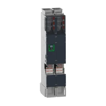
Control and supply wiring
The ATV9A0C25Q6: The control circuit requires an external 24 V DC supply (19–30 V) for digital inputs, with a separate internal 24 V DC rail (21–27 V) for STO and digital input power. A 10.5 V ±5% supply is provided for an external 1–10 kOhm reference potentiometer. Isolation between these supplies must be maintained; the STO supply is part of the safety chain. Control connections use removable screw terminals accepting 0.5–1.5 mm² (AWG 20–16). Line-side and motor connections are M10 bus bars. The drive is IP00 and intended for IP21 or IP54 cabinet integration per IEC 60529.
Communication and option slots
Slot A accepts fieldbus option cards covering Profibus DP V1, PROFINET, DeviceNet, EtherCAT, CANopen (RJ45, SUB-D 9, or screw terminals). Slots A/B/C accommodate digital/analog I/O or relay extension modules, and slot B accepts encoder interfaces (digital 5/12 V, analog, resolver). The base unit includes Modbus serial (RS-485, RTU, 4.8–38.4 kbit/s) and dual Ethernet ports with Modbus TCP/IP at 10/100 Mbit/s. This modular approach lets you match network topology without changing the drive core.