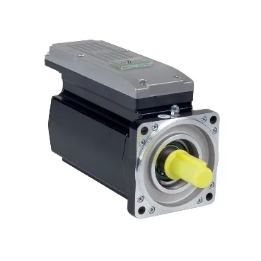
PacDrive 3 ILM, 1100 W with 28.3 N·m peak
The Schneider Electric ILM1003P21A0000 sits in the PacDrive 3 ILM family as a servo motor with integrated drive, sized at 1100 W nominal output power in a 100 mm flange with IP65 sealing — the integrated-drive class folds the amplifier into the motor housing so the cabinet loses a separate drive shelf and the field wiring collapses to power, feedback bus, and the safety circuit. Continuous torque is 5.8 N·m with 3.5 N·m nominal at 3000 rpm, and the peak stall torque reaches 28.3 N·m — so the working envelope runs roughly 8× from continuous to peak, which is the headroom sizing engineers look for on punch, indexing, and packaging axes that cycle through high-acceleration moves.
Current, impedance, and torque constant
Line current draws 2.4 A nominal against a 21.2 A Irms ceiling, with a continuous stall current of 3.6 A — the gap between nominal 2.4 A and the 21.2 A peak window is what permits short bursts into the 28.3 N·m peak torque without tripping the drive's I²T foldback. Torque constant sits at 1.61 N·m/A referenced to 120 °C, paired with a back-EMF constant of 103 V/krpm at 20 °C — at 3000 rpm nominal the back-EMF lands around 309 V, so pairing this motor with a 400 V-class PacDrive bus is the normal sizing, not a 230 V drive. Stator resistance is 2.6 Ohm phase-to-phase at 20 °C (1.81 Ohm phase-to-neutral at 120 °C) with 15.6 mH inductance phase-to-phase at 20 °C — those numbers set the electrical time constant and the current-loop bandwidth the PacDrive controller will tune around, not a buyer-side decision.
Feedback, poles, and rotor inertia
Feedback is a single-turn absolute SinCos Hiperface encoder with 128 periods of speed-feedback resolution and an 8-pole rotor — the single-turn absolute read means the controller knows absolute shaft position at power-up without a homing move, which matters on machines where referencing against a mechanical stop is impractical.
Mechanical fit on the machine
The motor flange is 100 mm with a 95 mm centring collar, an 11.2 in (285 mm) overall length, and four 9 mm mounting holes on the international standard flange — that geometry matches the standard IEC 100-frame footprint, so a retrofit onto an existing machine face does not require a machine rework. The shaft is 19 mm diameter by 40 mm long, untapped, with no second shaft end and no holding brake — an untapped shaft pushes the coupling choice toward a clamp-style or shrink-disk coupling rather than a keyed one, and the absent brake means the axis needs a regenerative or external mechanical brake if vertical-load holding is in scope. Shaft load limits are 1050 N radial at 1000 rpm, derating to 830 N at 2000 rpm and 730 N at 3000 rpm, with maximum axial force capped at 0.2 × Fr — those are the coupling-design constraints, since a belt drive or a long cantilevered coupling can push past the radial limit at the higher end of the speed range.
Cooling, sealing, and panel-side handling
Cooling is natural convection — no fan, no external air path — which keeps the motor sealed to IP65 and removes the dust-loading and filter-maintenance burden that plagues fan-cooled servo motors in dirty factory environments, while limiting continuous torque above the rated speed envelope compared with a force-ventilated equivalent. IP65 on the body means the motor tolerates low-pressure water jets and dust ingress, so it can sit close to the process on a packaging, filling, or washdown-adjacent line without a separate cover — but IP65 is not IP67, so the cordset entry and the feedback connector are the sealing-critical interfaces, not just the housing.