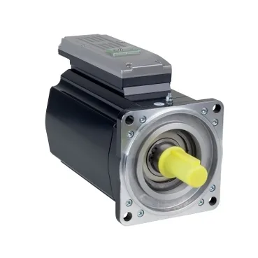
What's in the box when you bolt this down
The ILM1401P02A0000 is a Schneider Electric PacDrive 3 ILM integrated servo motor/drive — drive electronics and motor in one 254 mm long, 140 mm flange package, so the cabinet builder drops a single unit instead of a separate drive-and-motor pair. Lifecycle is current per the manufacturer record, so a panel quoting it today isn't pinning the BOM to a phase-out window.
Torque envelope and where it lives on the speed curve
Continuous torque is 4.6 N.m at 3000 rpm, so this is a mid-range axis — sized for packaging, indexing, and light converting lines rather than heavy machine-tool spindle duty. Peak stall torque of 27 N.m gives roughly 5.9x overload headroom for acceleration transients, which is what dictates whether the axis can punch through the move profile without the drive tripping on Irms. Continuous stall current is 4.7 A and nominal line current is 2.9 A, with a maximum Irms of 18.8 A — the drive sizing math always works off Irms, not the nominal figure, because that's what governs the acceleration profile. Torque constant of 1.6 N.m/A at 120 °C winding is the back-of-envelope check: peak torque divided by Kt gives the peak current the controller will command.
Feedback, electrical constants, and what they tell the commissioning engineer
Feedback is absolute multiturn SinCos Hiperface at 128 periods resolution — the controller reads absolute position from power-up, no homing move needed, which removes a startup step on every machine restart. Stator resistance is 1.81 Ω phase-to-phase at 20 °C, dropping the back-EMF constant to 108 V/krpm at the same reference temperature — drive bus sizing follows from that constant times top speed.
Shaft loads and the mechanical envelope
Shaft is 24 mm diameter x 50 mm long, untapped, with no second shaft end — coupling selection is straightforward, no keyseat to align. Maximum radial load is 2210 N at 1000 rpm, derating linearly to 1530 N at 3000 rpm, and axial load is capped at 0.2x Fr — overhung pulley or belt loads need that derating checked against the operating rpm before the coupling gets ordered.
Mounting footprint that drives the panel layout
International standard flange mount with a 130 mm centring collar and four 11 mm mounting holes on the 140 mm flange — a standard machine-tool foot pattern, so it drops onto the same bracket as the previous-generation ILM. Centring collar depth is 3.5 mm; the pilot registers cleanly into a mating flange bore before the bolts take load.