Schneider Electric LP5K12004BW3 — Contactors

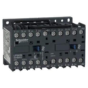
Schneider Electric LP5K12004BW3 TeSys K Changeover Contactor

MPNLP5K12004BW3
Obsolete

Schneider Electric TeSys K LP5K12004BW3 changeover contactor, 4-pole, 24 V DC coil, preassembled with reversing power busbar, screw clamp terminals, IP20.

Sourced new & surplus through independent channelsAuthenticity-screened · ESD-safe packingListing updated Jul 2026

Specifications

LP5K12004BW3 — Identification
ParameterValue
Product / component typeChangeover contactor
Series / rangeTeSys
ApplicationResistive load
LP5K12004BW3 — Ratings & Performance
ParameterValue
Rated operational voltage (Ue)Power circuit: 690 V AC 50/60 Hz
Utilisation categoryAC-1
LP5K12004BW3 — Contacts & Poles
ParameterValue
Pole configuration4P
LP5K12004BW3 — Environmental
ParameterValue
IP degree of protectionIP20 conforming to VDE 0106
Operating altitude2000 m without derating
Mechanical robustnessShocks contactor closed, on Z axis: 15 Gn for 11 ms conforming to IEC 60068-2-27 Shocks contactor opened, on Z axis: 10 Gn for 11 ms conforming to IEC 60068-2-27 Vibrations contactor closed: 4 Gn, 5...300 Hz conforming to IEC 60068-2-6 Vibrations contactor opened: 2 Gn, 5...300 Hz conforming to IEC 60068-2-6 Shocks contactor opened, on X axis: 10 Gn for 11 ms conforming to IEC 60068-2-27 Shocks contactor opened, on Y axis: 6 Gn for 11 ms conforming to IEC 60068-2-27 Shocks contactor closed, on X axis: 15 Gn for 11 ms conforming to IEC 60068-2-27 Shocks contactor closed, on Y axis: 10 Gn for 11 ms conforming to IEC 60068-2-27
Protective treatment / pollution degreeTC conforming to IEC 60068 TC conforming to DIN 50016
Flame retardanceV1 conforming to UL 94 Requirement 2 conforming to NF F 16-101 Requirement 2 conforming to NF F 16-102
LP5K12004BW3 — Approvals
ParameterValue
StandardsEN/IEC 60947-4-1 GB/T 14048.4 UL 60947-4-1 CSA C22.2 No 60947-4-1 JIS C8201-4-1
LP5K12004BW3 — Mechanical
ParameterValue
Width90 mm
Height58 mm
Depth57 mm

Product details

Rated for AC-1 resistive load duty, it breaks 110 A at 440 V and makes 144 A AC, with a rated insulation voltage of 690 V per IEC 60947-4-1 and 600 V per UL 508. The built-in bidirectional peak limiting diode suppressor handles coil suppression internally — no external flyback diode needed on the DC control circuit.

The 24 V DC control circuit operates between 0.7 and 1.30 Uc (roughly 16.8 to 31.2 V DC) and drops out between 0.1 and 0.7 Uc, so it holds in during brownout conditions down to about 17 V but releases reliably below 7 V. Mechanical durability is rated at 5 million cycles, with electrical durability of 300,000 cycles at 20 A AC-1 at up to 440 V — the mechanical life is the limit for dry switching or very light loads. The screw clamp terminals accept 1 to 2 conductors from 0.34 to 4 mm² (solid or flexible with/without ferrule), torqued to 0.8–1.3 N·m — standard for panel wiring with a No. 2 Phillips or 6 mm flat driver.

Mechanical interlocking is built in, preventing simultaneous closure of both contactors in a reversing pair — no external interlock relay needed.

Frequently asked questions

What are the key ratings I need to check for fit?

The 24 V DC coil, 4-pole changeover configuration, AC-1 resistive load rating (110 A breaking at 440 V), and the preassembled reversing busbar are the main fit criteria. The 90 x 58 x 57 mm DIN-rail footprint and screw-clamp terminals (0.34–4 mm²) determine panel integration.

What compliance documentation does this part carry?

It is certified to EN/IEC 60947-4-1, UL 60947-4-1, CSA C22.2 No. 60947-4-1, and JIS C8201-4-1. Flame retardance is UL 94 V1 and NF F 16-101/102 Requirement 2. The IP20 rating is per VDE 0106.

MPN
LP5K12004BW3