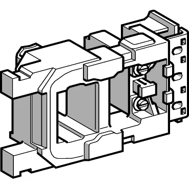
It's the part that pulls in the main contactor — no coil, no switching. Latching time runs 35...40 ms; unlatching takes 50...100 ms, which is standard for this frame size and means the contactor closes fast enough for motor starting but won't chatter on a marginal supply.
Coil resistance measures 129.3 Ohm at 68 °F (20 °C) on the latching winding and 10069 Ohm on the unlatching winding. That high unlatching resistance tells you this is a two-winding economizer design — the latching winding pulls the armature in, then the control circuit switches to the hold winding to keep it sealed with much less power draw. The control circuit voltage limits are 0.85...1.1 Uc for both latching and unlatching, so it holds in down to 408 V AC and up to 528 V AC.
This coil mounts into a TeSys F contactor frame — the same footprint as the LC1F range. It's a panel-mounted assembly, not DIN-rail, so the contactor body bolts to a backplate or sub-panel. The AC control circuit means no polarity concerns, but the two-winding design needs the correct control wiring sequence: power the latching winding first, then the control circuit transfers to the unlatching winding. If you're swapping a failed coil on a running line, verify the existing control wiring matches the latching/unlatching terminals before energizing.