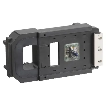
The LX9FL910 is a specific contactor coil in the TeSys F range, designed to pull in and hold the main contactor armature. It is the replaceable coil assembly for TeSys F contactors that require a 19...21 V DC control voltage. The coil uses low-consumption AC 40...400 Hz and DC technology, meaning it draws less steady-state current than a standard coil once the contactor is sealed. Rated control circuit voltage is 19...21 V DC. The operational limits span 0.85...1.1 Uc at 55 °C, so the coil must see at least about 16 V to pick reliably and can tolerate up to about 23 V. Drop-out occurs between 0.3...0.5 Uc, which means the contactor drops out cleanly between roughly 5.7 and 9.5 V — a wide hysteresis that prevents chatter on a sagging supply. Opening time is 60 ms, closing time 20 ms. That 3:1 ratio is typical for DC-operated contactor coils — the slower drop-out is inherent to the magnetic circuit decay. For applications where fast arc extinction matters (motor starting, capacitor switching), verify that 60 ms opening meets your coordination requirements.
Power draw and thermal management
Inrush power hits 733 W at 20 °C — that's the peak to overcome the air gap and seat the armature. Once sealed, hold-in power drops to 48 W at the same temperature. The difference between inrush and hold-in is what the low-consumption design achieves: the coil driver reduces current after pick-up, so the panel sees a fraction of the thermal load during continuous operation. Steady-state heat dissipation runs 22.8...27.8 W. That's the heat the coil dumps into the enclosure. In a densely packed panel, that 5 W spread matters for internal temperature rise — account for it in your thermal budget, especially if the contactor cycles near its maximum operating rate of 1800 cycles per hour at 70 °C. Mechanical durability is rated at 5 million cycles. That's the mechanical life of the coil assembly itself, not the contactor's electrical endurance under load. In a high-cycle application (sorting conveyor, press control), the coil will outlast the main contacts on heavy inductive loads.
Installation note — no built-in suppressor
The coil comes without a built-in suppressor module. That means you must add an external flyback diode or RC snubber across the coil terminals if the control circuit drives it from a PLC output or relay. Without suppression, the inductive kick from the coil can reach several hundred volts — enough to damage solid-state outputs or cause EMI issues on nearby sensors. A standard 1N4007 diode (cathode to positive) across the coil handles DC suppression cleanly.
Where it goes and what it tolerates
The coil is a DIN-rail-mounted accessory that snaps onto the TeSys F contactor body — no separate panel space required beyond the contactor footprint.