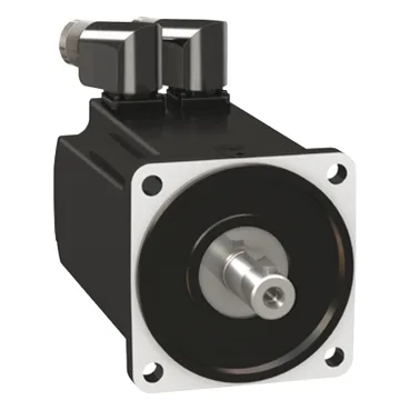
Motor construction and feedback for axis control
The MH31001P01F2200 is a three-phase servo motor from the MH3 series, sized for applications requiring 1520 W continuous power and a 100 mm international standard flange. The single-turn SinCos Hiperface encoder provides absolute position feedback within one revolution — the drive reads the rotor position at power-up without a homing move, which saves a cycle on every power cycle in single-turn applications. The holding brake (5.5 Nm holding torque) is integrated, so the motor holds the load at rest without external brake resistors or a separate brake controller. For vertical-axis or gantry builds, this brake is the primary safety element — the brake pull-in power is 12 W, and it engages when the drive removes the 24 VDC holding voltage.
Torque and speed — what the voltage-specific ratings mean for drive pairing
Nominal torque depends on the supply voltage and the drive model (LXM52 or LXM62). At 115 V single-phase the motor delivers 3.3 Nm; at 480 V three-phase it delivers 2.9 Nm. The torque constant is 1.09 Nm/A at 120 °C copper temperature — this is the conversion factor between the drive's current loop setpoint and the shaft torque. The continuous stall current is 3.15 A, so the drive's continuous current rating must exceed this value for sustained holding. Peak stall torque is 10.8 Nm across the 115–480 V three-phase range — this is the short-duration torque for acceleration or breaking through a mechanical bind. The maximum current Irms is 10.68 A, which the drive must be able to supply for the peak torque duration (typically 2–3 seconds per the drive's overload profile). Maximum mechanical speed is 6000 rpm, but the nominal speed is set by the drive and supply voltage combination — the motor can run at 1000, 2000, 4000, or 5000 rpm depending on the drive configuration. The back EMF constant is 70.3 V/krpm, so at 5000 rpm the motor generates 351.5 V line-to-line — the drive's DC bus must be higher than this to maintain current control.
Environmental sealing and mounting — IP65 and flange dimensions
IP65 standard means the motor housing is dust-tight and protected against low-pressure water jets from any direction. This suits food-and-beverage washdown zones, outdoor conveyor sections, or any floor area where coolant or cleaning spray hits the motor body. The rotatable right-angled connectors let the cable exit point be oriented after mounting — useful when the motor sits in a tight frame or against a machine wall. The 100 mm flange (3.9 in) with a 95 mm centring collar and 3.5 mm collar depth mates to standard IEC metric flanges. The four mounting holes are 9 mm diameter on the flange square. The smooth shaft is 19 mm diameter, 40 mm long — no keyway, so the coupling or pulley clamps onto the shaft with a friction lock. Maximum radial force at the shaft end is 900 N at 1000 rpm, derating to 530 N at 5000 rpm. Cooling is natural convection — no external fan or forced air. The continuous power rating of 1520 W assumes free airflow around the motor body; mounting in a confined pocket or against a heat source will require derating the continuous torque.
No official successor or cross-reference is recorded for this order code. The MH31001P sizing reference and MH3 device short name identify the motor family; any replacement within the family would require matching the flange size, shaft dimensions, encoder type, and brake voltage to the existing drive and mechanical mount.