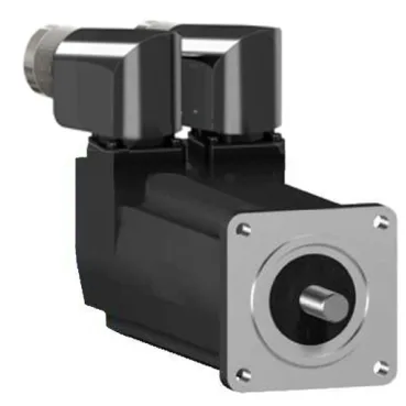
The SH30552P11F2000: Sourcing is straightforward: we quote this against your BOM quantity through authorized supply.
Speed and torque — voltage-dependent performance map
This motor's nominal speed depends entirely on what supply voltage you feed it. At 115 V single-phase it spins 2000 rpm; at 230 V single-phase it reaches 4000 rpm; on a three-phase supply (400 V or 480 V) it tops out at 8000 rpm. So the same motor covers both low-speed and high-speed machine axes — just match the drive voltage to the target speed. Nominal torque also shifts with voltage. At 115 V single-phase you get 0.77 N.m; at 230 V single-phase it's 0.75 N.m; on three-phase (400 V or 480 V) it settles at 0.63 N.m. The holding brake delivers 0.8 N.m regardless of supply — that's the torque that holds the load when power is off. Continuous power is 530 W, but nominal output power varies: 160 W on 115 V single-phase, 310 W on 230 V single-phase, 600 W on 400 V three-phase, and 670 W on 480 V three-phase. The 530 W continuous rating is the thermal limit under natural convection cooling — stay under it for sustained duty.
Encoder, brake, and IP rating — what you get in the package
The encoder is an absolute single-turn SinCos Hiperface type — no homing sequence needed on power-up; the position is known immediately. That saves a home-prox sensor and the wiring for it. IP rating is split: the motor body is IP65, so it handles washdown spray. The shaft bushing without a shaft seal ring is IP54 — that's splash-protected but not jet-proof. If the application sees direct water on the shaft exit, add an external seal or specify the IP65 shaft bushing option.
Mounting and connection — flange size and rotatable connector
The motor flange is 55 mm (2.2 in), conforming to the international standard flange pattern. Four mounting holes on a 5.5 mm diameter, centring collar 40 mm diameter and 2 mm deep — standard dimensions that fit most servo gearboxes and mounting brackets. Electrical connection is a rotatable right-angled connector — you can orient the cable exit in the direction that keeps the cable tray clean. No need for a separate right-angle adapter or a cable strain-relief bracket. Shaft is 9 mm diameter with a parallel key, 20 mm shaft length, 3 mm key width. The shaft end is parallel key — standard for positive drive coupling without set-screw slippage.
Thermal and electrical limits — what the windings can take
Stator resistance is 17.4 Ω and stator inductance is 18.2 mH — these set the electrical time constant and influence how the drive's current loop tunes. The torque constant is 0.59 N.m/A at 120 °C copper temperature; the back EMF constant is 40 V/krpm at 20 °C. Both matter when sizing the drive's voltage and current headroom. Maximum continuous current (Irms) is 4.8 A; the 3-second peak current is also 4.8 A — so this motor doesn't have a significant overload margin beyond its continuous rating. Peak stall torque is 2.5 N.m across the 115...480 V three-phase range; continuous stall torque is 0.71 N.m. The hot-spot copper temperature limit is 130 °C — the drive's thermal model should respect this.
Radial and axial load limits — bearing life planning
Maximum radial force at the shaft nose drops with speed: 370 N at 1000 rpm, 290 N at 2000 rpm, 260 N at 3000 rpm, 230 N at 4000 rpm, 220 N at 5000 rpm, 200 N at 6000 rpm, and 190 N at 7000 and 8000 rpm. Maximum axial force is 40 N. These are the limits for standard bearing life — belt drives or direct-coupled loads that exceed these will shorten bearing life.