Speed and torque across supply voltages
The SH30702P12F2100 delivers four distinct speed-torque envelopes depending on the supply: 1500 rpm at 115 V single-phase, 3000 rpm at 230 V single-phase, 6000 rpm at 400 V three-phase, and 7200 rpm at 480 V three-phase. Nominal torque drops from 2.15 N·m at 115 V to 1.8 N·m at 400/480 V three-phase, meaning the motor is wound for higher torque at lower voltages — useful if your line runs on a mixed-voltage plant floor and you need consistent force at the tool tip. Continuous power output climbs with voltage: 340 W at 115 V single-phase, 660 W at 230 V single-phase, 1190 W at 400 V three-phase, and 1360 W at 480 V three-phase. The 1130 W continuous power figure is a nominal midpoint; actual shaft power depends on the drive bus voltage and the duty cycle.
Brake, encoder, and mechanical interface
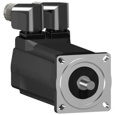
Position feedback comes from an absolute multiturn SinCos Hiperface encoder, which retains position through power cycles — no homing routine needed on startup. The encoder type suits applications where absolute position tracking across power loss is critical, such as tool changers or rotary indexing tables. The motor mounts on an international standard flange with a 70 mm square (2.8 in) pilot and a 2.5 mm centring collar depth. The shaft is 11 mm diameter with a parallel key, 23 mm shaft length, and 4 mm key width — a common IEC metric interface that mates with standard gearboxes and couplings without adapter plates.
Environmental protection and thermal limits
Cooling is natural convection, so no external fan or coolant lines are needed, but the motor must be mounted with free air circulation around the frame to stay within the 130 °C copper hot-spot limit. Maximum radial force at the shaft is speed-dependent: 710 N at 1000 rpm, dropping to 390 N at 6000 rpm. If you are belt-driving a load, the belt tension must stay below these limits at operating speed to avoid bearing overload. Maximum axial force is 80 N — direct-couple the load rather than using a thrust load from a helical gear.
Electrical parameters for drive matching
Stator resistance is 4.2 Ω and stator inductance is 29.65 mH — these values set the electrical time constant and influence the current-loop tuning gains in the servo drive. The torque constant is 0.7 N·m/A at 120 °C copper temperature, and the back EMF constant is 48 V/krpm at 20 °C. Maximum continuous current (Irms) is 11.8 A, with a 3-second peak current also rated 11.8 A — the motor is not overload-capable beyond its continuous rating, so acceleration torque must come from the drive's peak current capability, not the motor. Peak stall torque is 7.6 N·m across the 115-480 V three-phase range, while continuous stall torque is 2.04 N·m. The 3.7:1 peak-to-continuous ratio means the motor can deliver short bursts for acceleration without thermal damage, but sustained torque at the peak level will exceed the winding temperature limit.