Nominal torque and speed across supply voltages
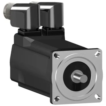
The SH30703M02A2000: This SH3 frame servo delivers 3.05 N.m nominal torque at 750 rpm on 115 V single-phase, and 2.63 N.m at 3000 rpm on 400 V three-phase. On 480 V three-phase it reaches 3600 rpm at the same 2.63 N.m — the torque curve is flat across the three-phase supply range, so the application speed determines the voltage choice, not the load capacity.
Encoder and feedback for position loops
Fitted with an absolute multiturn SinCos Hiperface encoder — single-cable feedback that carries both position and commutation data on the same pair. No homing sequence needed after a power cycle; the drive reads the absolute position on startup. The Hiperface protocol is standard across Schneider's Lexium drive family, so the motor pairs directly without a separate encoder converter.
Smooth shaft, no holding brake, natural convection
Smooth shaft end — no keyway, so the coupling bore must be sized for a clamping or friction fit. No holding brake fitted, so the load must be held externally or by the drive's holding torque at standstill. Cooling is natural convection; no forced-air or liquid circuit needed, but the duty cycle must stay within the thermal envelope of the 830 W continuous rating.
IP54 and IP65 protection variants
The motor carries IP54 on the shaft bushing without a shaft seal ring, and IP65 on the motor body and with a shaft bushing seal — both conforming to IEC 60034-5. For washdown or dust-prone environments, specify the sealed shaft bushing variant; the base build without the seal ring is splash-resistant but not jet-proof.
Stall torque and current for sizing the drive
Continuous stall torque is 2.94 N.m at 2.1 A continuous stall current — this is the holding torque at zero speed without exceeding the 130 °C copper hot-spot temperature. Peak stall torque reaches 11.3 N.m at 8.7 A for 3 seconds, which sets the peak current requirement for the servo drive. The torque constant is 1.4 N.m/A at 120 °C, so the drive's continuous current rating should be sized above 2.1 A plus the application's duty-cycle margin.
Radial and axial load limits
Maximum radial force Fr is 730 N at 1000 rpm, derating to 400 N at 6000 rpm — the bearing life follows the speed-force product. Maximum axial force Fa is 80 N. For belt-drive or overhung-load applications, check the resultant radial load against the speed-dependent curve; direct coupling typically stays well within the limit.
Mounting flange and dimensions
International standard flange, 70 mm square, with a 60 mm centring collar and 2.5 mm centring collar depth. Four mounting holes on a 5.5 mm diameter bolt circle. Overall length is 220 mm, shaft diameter 14 mm, shaft length 30 mm. The flange pattern matches standard 70 mm frame servo mounts — no adapter plate needed for common gearbox or machine interfaces.
Electrical parameters for drive tuning
Stator resistance is 10.7 Ohm and stator inductance is 27.65 mH — these set the electrical time constant and influence the current-loop tuning gains. Back EMF constant is 95 V/krpm at 20 °C, so at 3000 rpm the motor generates 285 V line-to-line; the drive DC bus must be high enough to overcome this voltage plus the IR drop at full current. Three motor poles — the electrical frequency at 3000 rpm is 75 Hz.
Connector options: straight or right-angle
Electrical connection is available as a straight connector or a rotatable right-angled connector — the right-angle option saves radial space in tight cable-tray or drag-chain layouts. Both are pre-wired at the factory; the connector type is specified at order and not field-swappable without replacing the motor cable assembly.