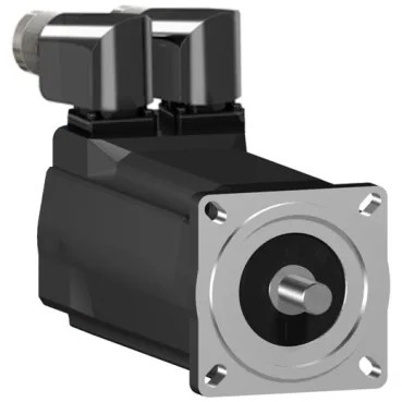
The SH30703P11F2100 is a three-phase servo motor from Schneider Electric's SH3 series, fitted with a holding brake — the brake is the deciding feature for any axis that must hold position under power loss or at standstill, such as a vertical lift or a gantry Z-axis. Nominal speed is 3000 rpm on a 230 V single-phase supply, 6000 rpm on 400 V three-phase, and 7200 rpm on 480 V three-phase — the speed range is supply-dependent, so the drive input voltage sets the achievable top speed for the application. Continuous stall torque is 2.94 N.m across the 115...480 V three-phase range, with a nominal torque of 2.1 N.m at 400 V and 480 V three-phase — the motor delivers full torque from stall up to rated speed, which is the torque envelope the load sees across the speed range. Peak stall torque reaches 11.3 N.m for short-duration overloads — this is the acceleration headroom for rapid moves or transient loads, limited to the 17.0 A peak current capability of the motor windings.
Feedback, sealing, and mechanical interface — the integration specs
The encoder is an absolute single-turn SinCos Hiperface type — this feedback protocol is common across Schneider and third-party drives that support Hiperface; single-turn means absolute position within one revolution, so the drive knows the rotor angle at power-up without a homing move. IP65 rating applies to both the motor body and the shaft bushing per IEC 60034-5 — the seal at the shaft exit is the wet-end barrier, so the motor withstands washdown spray and airborne dust without an additional cover. Mounting uses an international standard flange with a 70 mm flange size and a 2.5 mm centring collar depth — the pilot diameter and register depth match the standard B5 or B14 flange pattern, so the motor bolts directly to a gearbox or machine frame without an adapter plate. The shaft is 14 mm diameter with a parallel key, 5 mm key width, and 30 mm shaft length — the keyway transmits torque to the coupling or pulley; the shaft length and key dimensions must match the mating hub bore and keyseat depth.
Thermal and mechanical limits — derating and bearing load
Cooling is natural convection — no fan or forced air is required, which simplifies enclosure design and eliminates a failure point, but the continuous power rating of 1330 W assumes free airflow around the motor body; mounting in a confined pocket or against a panel reduces the thermal budget. Maximum radial force at the shaft is 730 N at 1000 rpm, derating to 400 N at 6000 rpm — this is the belt-tension or pulley side-load limit; exceeding it at the running speed shortens bearing life or causes shaft deflection. Maximum axial force is 80 N — for direct-drive or lead-screw applications, the thrust load on the bearing must stay below this figure; a thrust bearing on the load side is needed for higher axial loads.
Electrical parameters for drive commissioning
Stator resistance is 2.7 Ohm and stator inductance is 20.3 mH — these values set the electrical time constant and the current-loop tuning gains; the drive's auto-tuning routine typically measures them at standstill, but having the datasheet values allows a manual entry if the drive cannot run the test. Torque constant is 0.72 N.m/A at 120 °C copper temperature — this is the ratio of torque to current in the thermally hot condition; the cold torque constant is higher, so the drive's current limit must be set using the hot value to avoid thermal overload. Back EMF constant is 49 V/krpm at 20 °C — at 6000 rpm the motor generates 294 V line-to-line back EMF, which must stay below the drive's DC bus voltage to allow current control; a 400 V-class drive with a 560 V DC bus has headroom, but a 230 V-class drive does not at this speed. Maximum continuous current Irms is 17.0 A — this is the RMS current the windings can carry continuously at rated torque; the drive's continuous output current rating must match or exceed this value for full torque delivery.