Speed and torque across the supply range
The SH31002P01F1200: This motor's nominal speed climbs with the supply voltage: 1000 rpm on 115 V single-phase, 2000 rpm on 230 V single-phase, 4000 rpm on 400 V three-phase, and 4800 rpm on 480 V three-phase. That means the same frame covers both low-speed high-torque and high-speed low-torque applications — just match the drive voltage to the target speed. Nominal torque also shifts with voltage: 5.5 N.m at 115 V single-phase, 5.2 N.m at 230 V single-phase, 4.6 N.m at 400 V three-phase, and 4.4 N.m at 480 V three-phase. The torque drop at higher voltage is expected — the motor's continuous power is roughly constant, so higher speed means lower torque. Size the load against the torque at the operating voltage, not the peak stall number. Peak stall torque is 18.3 N.m across the 115–480 V three-phase range. That's the short-term overload for acceleration or breakaway — the drive must supply the peak current (17.1 A Irms) to hit it. The continuous stall torque is 5.8 N.m over the same range, so the motor can hold position at standstill indefinitely without overheating.
Brake, encoder, and feedback chain
The holding brake delivers 9 N.m (79.7 lbf.in) of static holding torque. That's enough to hold a vertical-axis load at standstill without power — no need for a separate brake resistor or mechanical lock. The brake is included in the motor, so there's no separate brake unit to mount or wire. Feedback comes from an absolute single-turn SinCos Hiperface encoder. Single-turn means absolute position within one revolution — the drive knows the shaft angle on power-up without a homing sequence. SinCos analog tracks give higher resolution than incremental encoders; the drive interpolates the sine/cosine signals for sub-micron positioning. The Hiperface protocol is common on Schneider and third-party drives, but confirm the drive's encoder interface supports it. The torque constant is 1.21 N.m/A at 120°C copper temperature. That's the hot motor's current-to-torque gain — use it for drive current-loop tuning. The back EMF constant is 77 V/krpm at 20°C; at 4000 rpm the back EMF reaches 308 V, which leaves about 50 V headroom on a 400 V DC bus (approx 560 VDC). If the application runs above 4000 rpm, the back EMF may saturate the drive's voltage limit and reduce available torque.
Mounting, cooling, and environmental rating
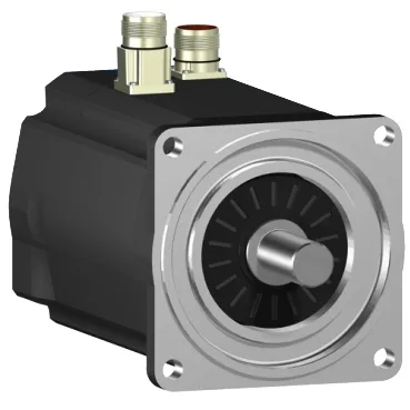
The motor uses an international standard flange with a 100 mm pilot diameter and a 95 mm centring collar. The centring collar depth is 3.5 mm — that's the register that locates the motor concentric to the load. Mounting holes are 9.0 mm diameter on the flange. The shaft is 19 mm diameter, 40 mm long, smooth (no keyway). Smooth shaft means the coupling or pulley must use a clamping or friction fit — no key to transmit torque. Cooling is natural convection — no fan, so the motor relies on free airflow around the frame. Don't box it in a tight enclosure without ventilation; the continuous power rating assumes ambient air can circulate. The IP rating is IP65 on the motor body and shaft bushing, IP67 on the housing. That means it's dust-tight and protected against low-pressure water jets (IP65) and temporary immersion (IP67). Suitable for washdown or outdoor duty, but the connector must be mated with the matching IP-rated cordset to maintain the seal. The electrical connection offers two options: a rotatable right-angle connector or a straight connector. The right-angle version helps in tight cable trays or when the motor is mounted close to a wall. The straight connector is simpler for straight-line cable routing. Both are connectorised — no hardwiring into a terminal box.
Bearing loads and mechanical limits
Maximum radial force Fr on the shaft depends on speed: 990 N at 1000 rpm, 790 N at 2000 rpm, 690 N at 3000 rpm, 620 N at 4000 rpm. Belt drives or direct-coupled loads must stay below this curve — exceeding it shortens bearing life. Maximum axial force Fa is 160 N — that's the thrust load the bearings can take, relevant for helical-gear or lead-screw drives.