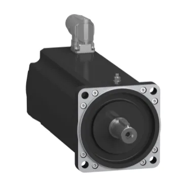
Three-phase servo with holding brake — 1930 W at 400 V
The SH31002P1AF4000 is a three-phase servo motor from the Schneider Electric SH3 family, fitted with a holding brake and an absolute single-turn Hiperface DSL encoder. It delivers 1930 W nominal output power when fed from a 400 V three-phase supply, with a nominal speed of 4000 rpm at that voltage. The speed-torque envelope shifts with the input voltage: at 230 V single-phase the nominal speed drops to 2000 rpm and nominal torque to 5.2 N·m; at 480 V three-phase the nominal speed rises to 4800 rpm with 4.4 N·m torque. This means the drive supply voltage directly sets the usable operating point — confirm the line voltage before committing the BOM. Continuous stall torque is 5.8 N·m across the 115–480 V three-phase range, with a peak stall torque of 18.3 N·m. The peak-to-continuous ratio of about 3:1 supports aggressive acceleration profiles, but the natural convection cooling (no fan) means sustained high-torque duty cycles will thermally saturate the 130 °C copper hot limit.
Shaft, flange, and coupling fit — 19 mm keyed shaft, 100 mm flange
The motor carries a 19 mm diameter shaft with a 6 mm parallel keyway, 40 mm shaft length, and 3.5 mm centring collar depth. The flange is the international standard 100 mm (3.9 in) pattern — this mates directly with standard SH3 gearboxes and mounting brackets without adapter plates. Maximum radial force at the shaft is 2420 N at 1000 rpm, derating to 1670 N at 3000 rpm. Axial force limit is 300 N. These set the coupling selection — an overhung load or belt drive must stay within the speed-dependent radial envelope to avoid bearing preload failure.
Encoder, connections, and environmental sealing
The absolute single-turn encoder uses Hiperface DSL — a digital serial link protocol over a single pair, carrying position and temperature data. No battery backup needed for single-turn absolute position within one revolution. The motor provides both a straight connector and a quicklock rotatable right-angled connector for the power and feedback cabling. IP65 on the motor body per IEC 60034-5, but the shaft bushing drops to IP54 when the shaft seal ring is not fitted. In washdown or coolant-mist environments, fit the optional shaft seal ring to maintain the full IP65 rating at the shaft exit. The holding brake delivers 9 N·m holding torque and draws 12 W pull-in power. This is a spring-applied, electrically released brake — power-off the brake coil to engage. The 12 W DC supply must be sized separately from the motor drive; a shared 24 VDC bus is typical, but confirm the brake release voltage matches the control voltage.
Electrical parameters for drive tuning and thermal protection
Stator resistance is 2.4 Ω per phase, inductance 13.5 mH — these set the current-loop PI gains in the servo drive. The torque constant is 1.21 N·m/A at 120 °C copper temperature, and the back EMF constant is 77 V/krpm at 20 °C. At higher speeds the back EMF approaches the DC bus voltage; the drive must have sufficient voltage headroom to maintain current regulation. Maximum continuous current (Irms) is 17.1 A, with the same value as the 3-second peak current. The motor is wound for 4 poles. Continuous power is 1930 W at 400/480 V three-phase, dropping to 1090 W at 230 V single-phase. The natural convection cooling limits the thermal time constant — oversize the drive's continuous current rating to at least 20 A for sustained operation near the peak torque region.
The sizing reference SH31002P anchors the family — this is the 100 mm flange, 1930 W variant with brake and absolute encoder. If the application does not require the holding brake, the equivalent motor without brake shares the same winding and flange dimensions; the brake-less variant will have lower total inertia and a shorter overall length.