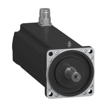
What this servo motor delivers that a brake-less variant cannot
The SH31003P1AF3100 is a three-phase servo motor from Schneider Electric's SH3 series, fitted with a holding brake rated at 9 N.m (79.7 lbf.in) — the brake holds the load at zero speed without power to the motor windings, essential for vertical-axis or gravity-loaded applications where a brake-less motor would coast or drop. Continuous power is 2400 W, with a continuous stall torque of 8 N.m (70.8 lbf.in) across the 115...480 V three-phase range, and a peak stall torque of 28.3 N.m (250.5 lbf.in) — the peak figure governs acceleration and emergency stop sizing, not the steady-state duty.
Encoder, feedback, and integration constraints
The motor ships with an absolute single-turn Hiperface DSL encoder — this is a digital serial-link feedback protocol that carries position and temperature data over a single pair, reducing cable count compared to incremental encoders with separate commutation tracks. Electrical connection is via a rotatable right-angled connector plus a quicklock straight connector — the rotatable option lets the cable exit in any of four orientations, which matters when the motor is mounted in a tight cabinet corner where a fixed connector would force a cable bend radius violation.
Speed, torque, and voltage dependence
Nominal speed varies with supply voltage: 2000 rpm at 230 V single-phase, 4000 rpm at 400 V three-phase, and 4800 rpm at 480 V three-phase — the motor's torque-speed curve is voltage-limited, so a 480 V line delivers higher top speed but the same continuous torque rating at that speed. Nominal output power also shifts: 1470 W at 230 V single-phase, 2390 W at both 400 V and 480 V three-phase — the 230 V single-phase figure is roughly 60 % of the three-phase rating, which affects machine cycle time if the line supply is single-phase only. Torque constant is 1.22 N.m/A at 120 °C (248 °F) copper temperature — this is the hot rating, not the 20 °C cold value, so the drive's current limit must be set to deliver the required torque at operating temperature, not at startup.
Mechanical interface and mounting
The motor uses an international standard flange with a 100 mm (3.9 in) flange size, a centring collar diameter of 95 mm (3.7 in) and depth of 3.5 mm (0.1 in), and four mounting holes of 9.0 mm (0.4 in) diameter — this matches the IEC 72-1 standard for frame size 100, so it bolts directly to common gearbox and machine interfaces without an adapter plate. Shaft dimensions: 19 mm (0.7 in) diameter, 40 mm (1.6 in) length, with a parallel key and a 6 mm (0.2 in) key width — the parallel key transmits torque to the load coupling; the keyway depth and fit class should be verified against the mating hub to avoid fretting under reversing loads. Maximum radial force Fr is 4500 N at 1000 rpm, 3570 N at 2000 rpm, and 3120 N at 3000 rpm — the bearing load limit drops with speed, so a belt-driven application at 3000 rpm must keep the belt tension below 3120 N to avoid premature bearing failure. Maximum axial force Fa is 740 N — this limits the thrust load from a helical gear or a leadscrew; exceeding it pushes the rotor against the bearing shield and increases friction or causes seizure.
No official successor or cross-reference is recorded — this is the current production part number.