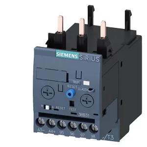
Siemens 3RB3123-4VB0 SIRIUS Solid-State Overload Relay, 40 A
Siemens SIRIUS 3RB3123-4VB0 solid-state overload relay, Size S0, 40 A rated thermal current, 690 V rated insulation voltage, adjustable trip classes CLASS 5E/10E/20E/30E, screw-type terminals, contactor mounting.
Specifications
| Parameter | Value |
|---|---|
| Product brand name | SIRIUS |
| Product designation | solid-state overload relay |
| Frame size (overload relay) | S0 |
| Combinable contactor sizes | S0 |
| Reference code (IEC 81346-2) | F |
| Parameter | Value |
|---|---|
| Overload current setting range | 10 ... 40 A |
| Trip class | CLASS 5E, 10E, 20E and 30E adjustable |
| Overload release type | electronic |
| Parameter | Value |
|---|---|
| Rated operational current | 40 A |
| Poles (main circuit) | 3 |
| Rated operating frequency | 50 ... 60 Hz |
| Rated insulation voltage (AC, pollution degree 3) | 690 V |
| Rated value (AC-3e), max. | 690 V |
| Rated surge withstand voltage | 6 kV |
| Main current circuit | screw-type terminals |
| Power loss at rated current (hot) | 3 W |
| Per pole | 1 W |
| Parameter | Value |
|---|---|
| Auxiliary contacts: NO | 1 |
| Auxiliary contacts: NC | 1 |
| Auxiliary contacts: CO (changeover) | 0 |
| Auxiliary switch short-circuit protection (required fuse) | fuse gG: 6 A |
| Switching current at 24 V | 2 A |
| Switching current at 60 V | 0.55 A |
| Switching current at 110 V | 0.3 A |
| Switching current at 120 V | 4 A |
| Switching current at 125 V | 0.3 A |
| Switching current at 220 V | 0.11 A |
| Switching current at 230 V | 3 A |
| Parameter | Value |
|---|---|
| Mounting / fastening method | Contactor mounting |
| Mounting position | any |
| Main-circuit connector arrangement | Top and bottom |
| Auxiliary/control circuit connection type | screw-type terminals |
| Removable aux./control terminal | Yes |
| Conductor cross-section: solid | 1x (0.5 ... 4 mm²), 2x (0.5 ... 2.5 mm²) |
| Conductor cross-section: solid or stranded | 1x (0,5 ... 4 mm²), 2x (0,5 ... 2,5 mm²) |
| Conductor cross-section: finely stranded with ferrule | 1x (0.5 ... 2.5 mm²), 2x (0.5 ... 1.5 mm²) |
| Conductor range (AWG), auxiliary contacts | 1x (20 ... 14), 2x (20 ... 14) |
| Parameter | Value |
|---|---|
| Operating temperature | -25 ... +60 °C |
| Storage temperature | -40 ... +80 °C |
| Transport temperature | -40 ... +80 °C |
| Relative humidity, operating | 10 ... 95 % |
| Max. installation altitude | 2 000 m |
| Shock resistance | 15g / 11 ms |
| Parameter | Value |
|---|---|
| Width | 45 mm |
| Height | 87 mm |
| Depth | 84 mm |
Product details
Frequently asked questions
How can I order the 3RB3123-4VB0 or check availability?
The 3RB3123-4VB0 is sourced to order against the BOM quantity through independent distribution.
What trip classes does the 3RB3123-4VB0 support?
The relay supports four adjustable trip classes: CLASS 5E, 10E, 20E, and 30E. This covers fast-starting motors (5E/10E) through high-inertia loads (20E/30E) without changing the relay hardware.
What this solid-state overload relay does
The Siemens 3RB3123-4VB0 is a SIRIUS solid-state overload relay — it protects motors by monitoring current and tripping on overload, with a configurable trip class that lets you match the relay to the motor's starting profile. The trip class is adjustable across CLASS 5E, 10E, 20E and 30E, so the same relay can handle fast-starting pumps (Class 10E) or high-inertia loads like centrifuges (Class 30E) without swapping hardware. The relay sits in the S0 frame size — the standard footprint for contactor mounting across the SIRIUS contactor range, so it mates directly with S0-size contactors without an adapter plate.
Trip class adjustability and what it means for the motor
The 3RB3123-4VB0 lets you set the trip class to 5E, 10E, 20E, or 30E — that's the maximum time in seconds the relay allows at 7.2× the current setting before tripping. A Class 10E setting trips in 10 seconds, which suits standard squirrel-cage motors starting direct-on-line; Class 20E gives 20 seconds for harder-starting loads like conveyors; Class 30E allows 30 seconds for high-inertia fans or crushers. The adjustment is on the relay face, no module swap needed. The trip threshold logic is straightforward: the motor current must stay above the lower current setting value and below the upper current setting value multiplied by 3.5. This means the relay trips when current exceeds the upper setting by a factor of 3.5 — a hard stall or phase-loss condition clears the motor off the line fast, while the adjustable class governs the thermal curve for normal overloads.
Panel fit and wiring details
Mounts directly onto the contactor — no DIN rail bracket needed. The S0 size means it occupies the same 45 mm width as the matching S0 contactor, keeping the motor starter assembly compact. The screw terminals use Pozidriv PZ2 screwdriver tip with a shaft diameter of 5 to 6 mm. Power dissipation is 1 W per pole — three poles total 3 W at rated current. That's low enough that no special ventilation is needed in a standard IP20 enclosure, but the heat does add to the panel's thermal budget if you're packing several starters in a small cabinet.
Shock resistance is 15 g for 11 ms on the main contacts (9 g for the signaling contact in tripped position), and vibration resistance per IEC 60068-2-27 covers 1-6 Hz at 15 mm amplitude and 6-500 Hz at 20 m/s² for 10 cycles. The relay carries a 'Note for message tripped' designation — meaning the auxiliary contact 97/98 changes state when the relay trips, giving a positive signal to the control system. This is the standard N/C alarm contact that opens on trip, used for remote fault indication.
The kit is complete: the relay ships with the screw terminals ready for the main circuit wiring, the auxiliary contact block is integrated, and the trip class selector is on the face. No separate accessory pack is needed for basic installation — just the matching S0 contactor and the control wiring.