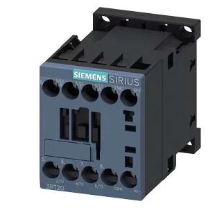
The main contacts carry the load for switching motor and resistive circuits. The contactor's size S00 rating covers the 20 A to 12 A range for main contacts, and the auxiliary switch handles DC breaking at various voltages: 10 A at 24 V, 2 A at 48 V and 60 V, 1 A at 110 V, 0.9 A at 125 V, 0.3 A at 220 V, and 3 A at 400 V. That DC auxiliary rating matters when switching DC control circuits or small DC loads downstream of a PLC output.
Duty-cycle and switching frequency
Switching frequency depends on the load type. At AC-1 (resistive) the contactor handles up to 1,000 operations per hour. For AC-2 (slip-ring motors) and AC-3 (squirrel-cage motors) the limit is 750 ops/h. At AC-4 (plugging/reversing/inching) it drops to 250 ops/h — the harsher the duty, the more thermal recovery time the contactor needs between cycles. The arcing time sits between 10 ms and 15 ms, and the DC coil dropout delay is 7 ms to 13 ms.
Wiring and clearances
The screw terminals accept solid or stranded copper: 0.5 mm² to 4 mm² for single conductors, or two conductors per terminal (2x 0.5–1.5 mm², 2x 0.75–2.5 mm², or 2x 4 mm²). That clearance is tight enough for dense panels, but the 10 mm vertical gap must be respected for arc-quenching and heat dissipation.