The coil is rated 24 V DC, and the magnet coil termination uses screw-type terminals. The contactor pulls in within 38 to 65 ms on DC and arcs in 10 to 15 ms; those timing figures matter if you are coordinating with other devices in a sequence. Main contact ratings are given at several DC voltages: 10 A at 24 V, 2 A at 48 V and 60 V, 1 A at 110 V, 0.9 A at 125 V, 0.3 A at 220 V, and 3 A at 400 V. These are the DC-1 or DC-13 style resistive/inductive loads the contactor can break — so if your load is a DC solenoid or small DC motor at 24 V, it handles 10 A; at higher voltages the current limit drops sharply. No auxiliary switch is built into this base unit, so if you need a feedback contact for the PLC, you will add an auxiliary contact block separately. Switching frequency limits depend on the duty class: 1000 cycles/hour at AC-1 (resistive), 750 at AC-2 and AC-3 (motor starting/running), and 250 at AC-4 (plugging/inching). For a motor switching application at AC-3, that is 750 operations per hour — enough for most conveyor or pump duty cycles. Spacing requirements are 10 mm upward/downward/forward, 6 mm at the side — so plan for those clearances to avoid heat buildup.
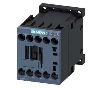
Siemens 3RT2017-1JB42 SIRIUS Contactor, Size S00, 24V Coil
MPN3RT2017-1JB42
Active
Siemens SIRIUS coupling contactor, Size S00, 24 V DC coil, screw-type terminals, 45 mm width, 73 mm depth, 58 mm height.
Source DocumentedChannel stated on listing & quote
Condition PhotosReal unit photos / video on request
WhatsApp AnswersFast human replies for machine-down parts
Worldwide DispatchDHL/FedEx — transit quoted per order
Independent China distributor & sourcing agent· Listing updated Sep 2026
Specifications
| Parameter | Value |
|---|---|
| Contactor frame size | S00 |
| Parameter | Value |
|---|---|
| Rated operational current, AC-12, max. | 10 A |
| Rated operational current, AC-4 @ 400 V | 8.5 A |
| Rated value @ 400 V | 3 A |
| Rated value @ 500 V | 2 A |
| Rated value @ 690 V | 1 A |
| Rated value @ 230 V | 2 hp |
| Rated value @ 24 V | 10 A |
| Rated value @ 60 V | 2 A |
| Rated value @ 110 V | 1 A |
| Rated value @ 220 V | 0.3 A |
| Parameter | Value |
|---|---|
| Control supply voltage type | DC |
| Parameter | Value |
|---|---|
| Main poles | 3 |
| Main NO contacts | 3 |
| Auxiliary contact reliability | 1 faulty switching per 100 million (17 V, 1 mA) |
| Parameter | Value |
|---|---|
| Short-circuit coordination type 1, fuse | gG: 50A (690V,100kA), aM: 20A (690V,100kA), BS88: 35A (415V,80kA) |
| Short-circuit coordination type 2, fuse | gG: 20A (690V,100kA), aM: 16A (690V, 100kA), BS88: 20A (415V, 80kA) |
| Aux. switch short-circuit protection, fuse | gG: 10 A (500 V, 1 kA) |
| Parameter | Value |
|---|---|
| Main circuit connection | screw-type terminals |
| Aux. / control circuit connection | screw-type terminals |
| Conductor cross-section, solid | 0.5 ... 4 mm² |
| Conductor cross-section, solid or stranded | 2x (0.5 ... 1.5 mm²), 2x (0.75 ... 2.5 mm²), 2x 4 mm² |
| Conductor cross-section, finely stranded w/ ferrule | 2x (0.5 ... 1.5 mm²), 2x (0.75 ... 2.5 mm²) |
| Mounting method | screw and snap-on mounting onto 35 mm DIN rail according to DIN EN 60715 |
| Side-by-side mounting | Yes |
| Parameter | Value |
|---|---|
| Durability (operating cycles, typ.) | 30 000 000 |
| Parameter | Value |
|---|---|
| Operating temperature range | -25 ... +60 °C |
| Storage temperature range | -55 ... +80 °C |
| Installation altitude, max. | 2 000 m |
| Parameter | Value |
|---|---|
| Width | 45 mm |
| Height | 58 mm |
| Depth | 73 mm |
Product details
Frequently asked questions
What wire sizes does the coil terminal accept?
The screw-type terminals accept solid or stranded wire from 0.5 to 4 mm², and also 2x (0.5 to 1.5 mm²), 2x (0.75 to 2.5 mm²), or 2x 4 mm² for paralleled conductors.
What are the main contact ratings at 24 V DC?
At 24 V rated value, the main contacts are rated for 10 A. At 48 V and 60 V it drops to 2 A, and at 110 V to 1 A.
Does this contactor include an auxiliary switch?
No, the base unit 3RT2017-1JB42 has no auxiliary switch. You will need to add a separate auxiliary contact block if feedback is required.
What is the mounting method and size?
It mounts via screw and snap-on onto 35 mm DIN rail per DIN EN 60715. The Size S00 frame measures 45 mm wide, 73 mm deep, and 58 mm high.
What is the operating temperature range?
Operation is rated from -25 to +60 °C, storage from -55 to +80 °C.
MPN
3RT2017-1JB42