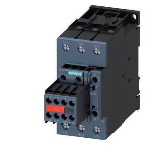
It mounts on a standard 35 mm DIN rail per DIN EN 60715, either screwed down or snapped on, and the mounting position is flexible: +/-180° rotation on a vertical surface, plus +/-22.5° tilt forward or backward.
Switching duty and mechanical life
Maximum switching rates: AC-1 at 1,000 cycles/hour, AC-3 at 800 cycles/hour, AC-4 at 250 cycles/hour. Mechanical life typical at 10 million operations.
Clearances and environmental limits
Spatial clearances around the contactor: 10 mm upwards, downwards, and forwards; 6 mm at the sides. The auxiliary switch is not included — this is a bare main contactor.
Main contact screw terminals accept 2x (0.5-1.5 mm²) or 2x (0.75-2.5 mm²) solid or stranded conductors. The contactor has 18-1 main contacts.
Coil suppression note
The DC coil draws 6 A at 24 V rated value, dropping to 2 A at 48 V and 60 V, 1 A at 110 V, and 0.9 A at 125 V. At 220 VDC the holding current is 0.3 A. For a 24 VDC control circuit, verify the power supply can deliver the 3 A inrush peak on pickup — a standard 24 VDC bus with a 3 A headroom per contactor is safe. No built-in suppression; add a free-wheel diode across the coil if the PLC output or relay driving it lacks internal clamping.