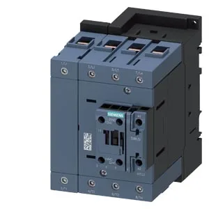
What it is and where it fits
The Siemens 3RT2348-1NB30 is a SIRIUS contactor in size S3, designed for switching motor loads and resistive loads in industrial control panels. It mounts via screw or snap-on onto 35 mm DIN rail per DIN EN 60715, which is the standard rail profile across most panel builds. The coil accepts 20 to 33 V AC/DC, drawing 3.5 VA at both 50 Hz and 60 Hz, with an inrush peak of 6.5 A. That 3.5 VA hold power is the same at both line frequencies, so no derating needed when switching between 50 Hz and 60 Hz supply regions. Operating temperature range is -25 to +60 °C; storage range is -55 to +80 °C. The storage spec is wider than the operating range, which is typical for handling and shipping — the part can sit in a cold warehouse or hot truck without damage.
Key ratings and what they mean for your BOM
Size S3 is the frame size. The main contacts are rated for 10 to 2 A. The auxiliary contact block is built in (yes on auxiliary switch), with screw-type terminals. The auxiliary contacts are rated at specific voltages: 10 A at 24 V, 2 A at 48 V, 6 A at 60 V, 1 A at 110 V, 0.9 A at 125 V, 0.3 A at 220 V, and 6 A at 230 V. These are the switching capacities for the auxiliary circuit — important for interlocking, status feedback to a PLC, or signaling to a downstream contactor. The 10 A at 24 V is generous for a 24 VDC control loop; the 0.3 A at 220 V is typical for a 220 VAC pilot light or relay coil. Mechanical life is 10,000,000 operations typical.
Mounting and wiring details
Dimensions: 140 mm high, 96 mm wide, 152 mm deep. The 96 mm width is three 32 mm modules wide on a DIN rail — standard for a size S3 contactor. The 152 mm depth includes the coil terminals and any auxiliary block; check clearance behind the panel door. Required clearances: 10 mm upwards, 10 mm downwards, 20 mm forwards, and 10 mm at the side. These are minimum air gaps for heat dissipation and arc quenching — don't crowd the contactor against other components or the enclosure wall. Main circuit wiring accepts stranded conductors from 6 to 70 mm². Auxiliary circuit wiring accepts solid conductors: 2x (0.5 to 1.5 mm²) or 2x (0.75 to 2.5 mm²). The 70 mm² main terminal is large enough for a 50 A feed; the auxiliary terminals are sized for standard control wiring. Mounting position is flexible: +/-180° rotation on a vertical surface, and can be tilted forward/backward by +/-22.5° on a vertical surface. This helps when the contactor must be mounted at an angle in a tight cabinet or on a swing frame. Up to 2 auxiliary switches can be attached. The opening time is 38 to 57 ms for both AC and DC operation; arcing time is 10 to 20 ms. The operating range factor is 0.8 (initial) to 1.1 (full-scale) of rated voltage.
Sourcing and lifecycle
Sourcing is straightforward: quoted to order against an RFQ. No last-time-buy constraints, no broker-channel dependency. If you're freezing a BOM for a new line or filling an MRO spare, this is a clean active part to specify.