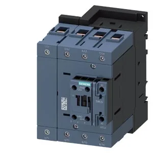
Siemens 3RT2348-1NF30 — Contactors

Siemens 3RT2348-1NF30 SIRIUS Contactor, Size S3, 83-155V AC/

MPN3RT2348-1NF30
Active

Siemens SIRIUS contactor, size S3, 3RT2348-1NF30, 83-155 V AC/DC coil, screw-type terminals, screw and snap-on mounting onto 35 mm DIN rail.

Sourced new & surplus through independent channelsAuthenticity-screened · ESD-safe packingListing updated Aug 2026

Specifications

3RT2348-1NF30 — Identification
ParameterValue
Contactor frame sizeS3
3RT2348-1NF30 — Ratings & Performance
ParameterValue
Rated operational current, AC-12, max.10 A
Rated value @ 400 V3 A
Rated value @ 500 V2 A
Rated value @ 690 V1 A
Rated value @ 230 V6 A
Rated value @ 24 V10 A
Rated value @ 60 V6 A
Rated value @ 110 V1 A
Rated value @ 220 V0.3 A
3RT2348-1NF30 — Control & Coil
ParameterValue
Control supply voltage typeAC/DC
Rated value @ 50 Hz3.5 VA
Rated value @ 50 Hz83 ... 155 V
3RT2348-1NF30 — Contacts & Poles
ParameterValue
Main poles4
Main NO contacts4
Auxiliary contact reliability1 faulty switching per 100 million (17 V, 1 mA)
3RT2348-1NF30 — Protection & Coordination
ParameterValue
Short-circuit coordination type 1, fusegG: 250 A (690 V, 100 kA)
Short-circuit coordination type 2, fusegR: 250 A (690 V, 100 kA)
Aux. switch short-circuit protection, fusegG: 10 A (690 V, 1 kA)
3RT2348-1NF30 — Connection & Mounting
ParameterValue
Main circuit connectionscrew-type terminals
Aux. / control circuit connectionscrew-type terminals
Conductor cross-section, solid2x (0.5 ... 1.5 mm²), 2x (0.75 ... 2.5 mm²)
Conductor cross-section, solid or stranded2x (0.5 ... 1.5 mm²), 2x (0.75 ... 2.5 mm²)
Conductor cross-section, finely stranded w/ ferrule2x (0.5 ... 1.5 mm²), 2x (0.75 ... 2.5 mm²)
Mounting methodscrew and snap-on mounting onto 35 mm DIN rail according to DIN EN 60715
Side-by-side mountingYes
3RT2348-1NF30 — Durability
ParameterValue
Durability (operating cycles, typ.)10 000 000
Durability with aux. switch block (cycles, typ.)10 000 000
3RT2348-1NF30 — Environmental
ParameterValue
Operating temperature range-25 ... +60 °C
Storage temperature range-55 ... +80 °C
Installation altitude, max.2 000 m
3RT2348-1NF30 — Mechanical
ParameterValue
Width96 mm
Height140 mm
Depth152 mm
3RT2348-1NF30 — Specifications
ParameterValue
At AC38 ... 57 ms

Product details

The coil accepts AC or DC from 83 to 155 V, pulling 3.5 VA at both 50 and 60 Hz. That wide-range coil simplifies stocking — one part covers a spread of control voltages common in European and North American panels. Envelope is 140 mm high by 96 mm wide by 152 mm deep. The depth matters when you're routing wires past a gland plate or trying to squeeze a row of contactors into a shallow enclosure — 152 mm is not a shallow-mount part.

Main contacts accept stranded wire from 6 to 70 mm² — that's a heavy lug range, sized for the S3 frame's current handling. The auxiliary switch is built in, with contacts rated at 10 A at 24 V, 6 A at 60 V, 6 A at 230 V, and 3 A at 400 V. Mechanical life is listed at 10 million operations typical. That's a high-cycle figure — suitable for frequent start/stop applications like conveyor indexing or pump cycling, not just infrequent isolation. The storage range is wider — that's the handling and shipping limit, not the running limit.

Skimp on those and you lose airflow and arc clearance. Solid wire termination on the aux/coil terminals accepts 2x (0.5 to 1.5 mm²) or 2x (0.75 to 2.5 mm²). The coil terminals are screw-type — no spring cages here, so torque them to spec and avoid stranded whiskers shorting to the frame.

Frequently asked questions

What are the key ratings for the auxiliary contacts?

The auxiliary contacts are rated at 10 A at 24 V, 2 A at 48 V, 6 A at 60 V, 1 A at 110 V, 0.9 A at 125 V, 0.3 A at 220 V, 6 A at 230 V, and 3 A at 400 V. These values determine whether the aux can directly drive a load at your control voltage.

What is the coil voltage range and type?

The coil accepts AC or DC voltage from 83 to 155 V. It draws 3.5 VA at both 50 Hz and 60 Hz.

What are the mounting dimensions and clearances?

The contactor measures 140 mm high by 96 mm wide by 152 mm deep. Required clearances are 10 mm upwards, 10 mm downwards, 20 mm forwards, and 10 mm at the side.

MPN
3RT2348-1NF30