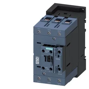
SIRIUS S3 Contactor, Current Production
At 140 mm high, 70 mm wide, and 152 mm deep, this S3 frame occupies a standard contactor footprint. The 70 mm width means it takes up three or four 22.5 mm-wide modular device slots on the DIN rail — plan your rail layout accordingly. Power circuit wiring accepts stranded conductors from 6 to 70 mm² — that's a serious lug range, covering everything from a 4 mm² motor feed up to a 70 mm² feeder. The coil and auxiliary terminals use screw-type terminals accepting 2x (0.5 to 1.5 mm²) solid or 2x (0.75 to 2.5 mm²) stranded. Keep your ferrule sizes within that range for a reliable connection.
Auxiliary Contact Ratings — What They Mean
The built-in auxiliary switch is rated for different currents depending on the control voltage. At 24 V AC (50 Hz) it's rated 10 A — that's your typical PLC or relay coil load. For DC control circuits, the ratings are lower: 2 A at 48 V, 1 A at 110 V, and only 0.1 A at 600 V. These are the make/break capacities for the auxiliary contacts; don't assume the 10 A figure applies at higher voltages. The contactor carries one instantaneous auxiliary contact (NO or NC — the evidence doesn't specify which, but typically one NO on the base unit).
Environmental and Coil Specs
The coil is AC-operated at 24 V, 50 Hz — verify your control transformer matches.