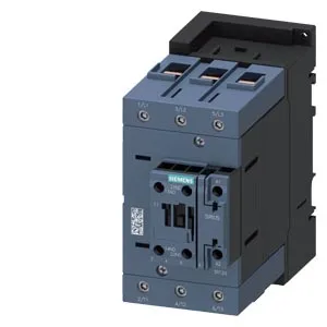
SIRIUS S3 contactor — 110 VAC coil, 6–70 mm² power wiring
This is a Siemens SIRIUS 3RT2446-1AF00 contactor in frame size S3, with a 110 V 50 Hz AC coil terminated via screw-type terminals. The main power circuit accepts stranded conductors from 6 to 70 mm², covering the range from moderate motor feeds up to a 70 mm² incoming cable. The auxiliary contact block carries one instantaneous normally-open contact, and the contactor is also equipped with an auxiliary switch — check the specific NO/NC count against your control scheme. The coil draws 10 A at 24 V rated value, stepping down to 0.1 A at 600 V rated value, so the control transformer sizing follows the inrush at the pick-up voltage.
Panel layout — DIN rail, clearances, and side-by-side mounting
Mounts via screw or snap-on onto 35 mm DIN rail per DIN EN 60715. The envelope is 70 mm wide, 140 mm high, 152 mm deep — the depth dimension is the critical one for enclosure depth selection. Side-by-side mounting is permitted, so you can gang multiple contactors on the same rail without forced spacing. Clearance distances: 10 mm upwards and downwards, 10 mm at the sides, 20 mm forwards. The mounting position allows ±180° rotation on a vertical surface and ±22.5° tilt forward/backward — useful when the panel layout forces an unconventional orientation. Operating temperature range is -25 to +60 °C, storage from -55 to +80 °C. The arcing time is 10–20 ms, and the mechanical endurance is rated at 10 million typical operations — a solid baseline for high-cycle applications like conveyor or pump control.
Switching capacity across the voltage range
The contactor's rated switching current varies with the applied voltage. At 24 V it switches 10 A; at 230 V it handles 6 A; at 400 V it is rated for 3 A; at 690 V it drops to 1 A. For DC circuits, at 48 V and 60 V it is rated 2 A, stepping down to 0.1 A at 600 V. These figures define the load envelope — match them against your motor full-load current and the voltage class of the circuit. The coil's power factor at 50 Hz is 0.38 — a relatively low figure that means the coil draws more apparent power than its real power consumption suggests. Factor this into the control transformer VA rating, especially when multiple contactors pick up simultaneously.
Sourcing and lifecycle — current production, quoted to order
The auxiliary terminals accept 2x (0.5–1.5 mm²) solid or 2x (0.75–2.5 mm²) stranded wire — the same spec applies to the coil terminals. This covers standard control wiring up to 2.5 mm², which is adequate for most 110 VAC control circuits within a panel.