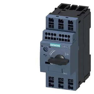
That 100 kA breaking capacity at 400 V (and at 240 V, 500 V) tells you it can sit upstream of a fault without needing a backup fuse for most industrial distribution; at 690 V it still holds 10 kA, enough for 690 V line-side applications. Dimensions are 45 mm wide, 106 mm tall, 97 mm deep. Clearance: 50 mm upward and downward, 30 mm at the side, zero forward and backward.
That's SCCR-level capability for most industrial panels. The 15 operations per hour maximum at AC-3 duty (and AC-3e) sets the switching pace — fine for a motor start/stop cycle, not for rapid reversing or jogging duty. Spring-loaded terminals accept 2x (0.5 to 2.5 mm²) solid or stranded — typical for control wiring up to 14 AWG. No ferrule needed, but stranded wire benefits from one for consistent insertion.
Mounts in any position — vertical, horizontal, upside-down — the breaker's thermal-magnetic trip curve doesn't care about orientation. Side clearance of 30 mm to adjacent devices is the minimum for heat dissipation. Spring terminals on the main circuit mean no screwdriver calibration — strip to 8-10 mm, push in. The auxiliary contact block (if added) shares the same spring-clamp interface. Verify the wire ferrule size against the 2.5 mm² maximum before terminating.