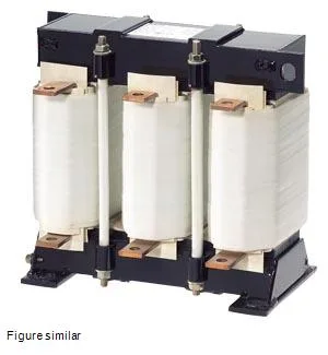
What this choke does in a drive line
It limits current rise (di/dt) and reduces harmonics on the line side of a variable-frequency drive or DC drive supply. Rated for 180 A continuous at 400 V AC, 50 Hz, with a maximum current of 200 A and an inductance of 0.14 mH per phase. The 4% relative inductive voltage drop (uk) at rated current is the key sizing parameter — it tells you the choke will drop about 4% of line voltage under full load, which is typical for drive input reactors meant to smooth commutation notches without excessive voltage sag.
The AC rated current of 180 A is the continuous thermal limit at 40 °C ambient. The DC rated value of 245 A applies when the choke is used in a DC link circuit — common in regenerative or battery-backed drive configurations. Total power loss splits between the coil (167 W) and the iron core (85 W), summing to 252 W that must be dissipated into the surrounding air. IP00 means no enclosure; the choke is intended for mounting inside a ventilated cabinet where the heat can rise out. Thermal class H (IEC 60085) means the insulation system can handle 180 °C hot-spot temperature, giving margin above the 40 °C ambient for the internal temperature rise.
Mounting dimensions: 0.27 m wide × 0.248 m tall × 0.187 m deep. The flat-type terminals accept busbar or cable lugs — no screw-clamp wire termination. Because the choke is IP00 and dissipates 252 W, it needs clearance around all sides for natural convection; do not nest it against other heat-generating components. The 0.14 mH inductance per phase is fixed — no taps or adjustment. Verify that the 4% voltage drop at rated current is within the drive input voltage tolerance before specifying.