What you're sourcing
The 6ES7142-3BH00-0XA0 is a distributed I/O node with 16 digital outputs on a PROFIBUS DP slave, a 24 V DC rated supply, a 0.5 A per-channel output rating, 4/5-pin M12 circular connectors, IP65/67 housing, and 60 × 210 × 28 mm dimensions.
Output ratings and what they govern
Each of the 16 outputs is rated 0.5 A for a signal '1', with a typical per-channel response threshold of 1.4 A feeding the short-circuit protection. Switching frequency is three different numbers depending on load: 100 Hz on a resistive load, 0.5 Hz on an inductive load per IEC 60947-5-1 DC-13, and 1 Hz on a lamp load — pick the one that matches the actuator, not the headline. Inductive shutdowns are clamped to 2L+ (-47 V), and the 0.1 mA max residual current at signal '0' keeps the off-state leakage from holding sensitive DC loads.
PROFIBUS DP and node behaviour
PROFIBUS DP runs up to 12 Mbit/s with the full baud ladder from 9,6 kbit/s to 12 Mbit/s, and the DP interface is isolated from the other on-board circuit components. The two supplies draw separately: 70 mA typical from 1L+ and 80 mA typical from 2L+ with no load, total power loss 4 W — budget both rails on the field power distributor rather than only the logic feed. Diagnostic information is readable over the bus, a group-error LED (SF, red) sits on the front, and per-channel fault indicators (F, red) are not present on this variant — fault triage is at the channel-mapping level in the controller, not the face of the node. Reverse-polarity protection is in place on the supply path, and the channels support controlling a digital input as well as redundant control of a load — useful for safety handshakes wired into the same M12 drop.
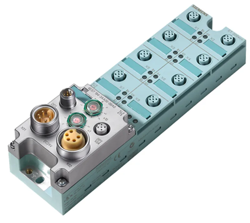
Field-mount envelope and wiring
The housing is sized for cabinet-free mounting: 60 mm wide, 210 mm tall, 28 mm deep, IP65/67 — install it on the machine frame close to the actuators and the M12 drops carry signal and load together, with PROFIBUS DP running up to 30 m on unshielded cable between nodes. Isolation between different circuits is rated 75 V DC / 60 V AC, and the bus interface is tested with 500 V DC — keep field wiring and PROFIBUS cable routed to preserve that separation on the machine. A channel-to-channel fault LED is not provided (F indicator marked 'No'), so the swap decision comes from the controller diagnostic buffer plus the green per-channel status indicator, not from a red dot on the slice.
Spec at a glance
Alarms are not part of the feature set on this node and there is no inter-channel isolation — group your loads accordingly when you lay out the M12 pin assignments.