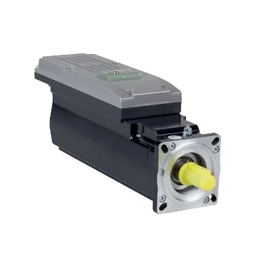
Where this motor lands on the machine
The ILM0702P22F0000 is a Schneider Electric PacDrive 3 ILM integrated drive motor — the drive electronics sit on the back of the motor rather than in a separate cabinet, so the loop between position feedback and the power stage stays short and the cabinet build drops one component. It is sized for the compact axis: a 2.8 in (70 mm) flange, 9.9 in (252 mm) overall length, 0.7 in (18 mm) key width on an untapped 0.4 in (11 mm) shaft with no second shaft end — the mechanical envelope that typically drives a small-format indexing table, a labelling head, or a packaging-format servo. International standard flange mounting with four 0.2 in (5.5 mm) holes and a 2.4 in (60 mm) centring collar mean the motor drops onto the common NEMA-style footprint without a custom adapter plate.
Headline ratings and what they mean at the load
Continuous torque is 1.15 N.m (10.18 lbf.in) at a nominal 6000 rpm, drawing 1.5 A line current with 720 W of continuous shaft output — that is the operating point the servo drive loop is sized around, not the peak. Peak stall torque is 7.6 N.m (67.3 lbf.in), so the motor can deliver roughly six times nominal torque for the acceleration pulse; the drive limit at 11.8 A Irms is what caps how long that pulse can be held before thermal foldback starts. Continuous stall torque of 1.7 N.m (15.05 lbf.in) at 2.5 A tells the integrator how much torque is available at zero speed with the winding hot — relevant when the axis has to hold position against a static load, for example a vertical format change-over. Back EMF constant of 48 V/krpm at 20 °C and stator resistance of 4.2 Ohm Ph/Ph at 20 °C set the bus-voltage headroom — a 320 VDC PacDrive bus keeps the motor safely out of field-weakening across the full 6000 rpm speed range.
Feedback, brake, sealing, and cooling
Absolute multiturn SinCos Hiperface feedback is the single-cable resolver-equivalent that keeps absolute position on power-up without a homing routine — worth noting for any machine where a lost home position on restart costs a full format change. A holding brake is fitted (3 N.m / 26.6 lbf.in), so the axis can be held in position with the drive stage de-energised; sizing the brake torque against the load inertia is the integrator's call, not the motor's. Cooling is natural convection — no integrated fan — so the motor relies on the flange to dump heat into the machine structure; in a sealed enclosure the continuous torque figure above needs to be derated against the ambient. IP65 sealing at the body means the motor tolerates dust and low-pressure water jets, which covers most washdown-adjacent packaging lines but stops short of the high-pressure cleaning that would call for IP67.
Rotor inertia and shaft loading limits
Maximum radial force Fr drops from 710 N at 1000 rpm to 390 N at 6000 rpm, and maximum axial force Fa is limited to 0.2 × Fr — these curves are the ones to check against a pulley or pinion mounted on the shaft overhang, not the headline torque figure.