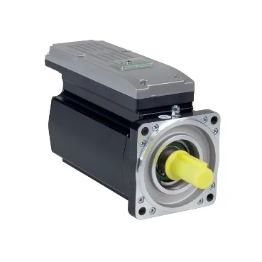
What the part is — and why PacDrive 3 is the lead
The ILM1002P11F0000 is the short name ILM on a PacDrive 3 range servo motor integrated drive from Schneider Electric; the lifecycle stage reads current on the record, which is the only signal procurement gets on paper before an RFQ is opened. An integrated drive — motor plus drive electronics on a single shaft — removes the separate amplifier cabinet and the long motor cable that drags a radiated-emissions signature through the panel; the ILM line carries its own back-EMF and torque constants so the controller parameter set can be loaded without a separate motor ID step.
Headline ratings — power, torque, speed
Nominal output is 910 W at 3000 rpm with a continuous stall torque of 4.4 N·m and a peak stall torque of 18.3 N·m — the roughly 4:1 peak-over-continuous headroom is the envelope inside which a PacDrive 3 motion profile can accelerate a packaging-line, pick-and-place, or short-stroke feed axis without saturating the current loop. Maximum current Irms is 13.1 A against a line-rated current of 2 A and a continuous stall current of 2.9 A — the Irms ceiling is the peak the drive will source for acceleration bursts while the continuous figures govern steady-state thermal sizing.
Feedback, brake, and the electrical constants the controller needs
Position feedback is absolute single-turn SinCos Hiperface — single-turn means absolute position within one revolution without battery backup, which suits rotary axes that do not need to retain absolute position across power cycles; Hiperface is the protocol the PacDrive 3 drive expects on commissioning. The holding brake provides 5.5 N·m of holding torque — sized to hold the vertical axis in place with the motor de-energised, which is the fail-safe state machine builders usually design to on packaging and small-format handling axes. Stator resistance and inductance are given at both 20 °C and 120 °C; the temperature split lets the PacDrive commissioning tool place the current-loop gains with the cold figure first and the warm figure for thermal compensation — without both values the gain scheduler can drift a few percent across a warm-up shift.
Mechanical fit into the machine
International standard flange mounting on a 100 mm motor flange, keyed shaft at 19 mm diameter and 40 mm shaft length, with four 9 mm mounting holes and a 95 mm centring collar 3.5 mm deep — that geometry mates to the standard NEMA-derived footprint common on small-format packaging, labelling, and pick-and-place gearboxes, so a replacement on an existing axis drop-in is the usual path. Overall length is 280 mm with a 30 mm key width on the keyed shaft; the second-shaft end is not provided — relevant where a manual handwheel or auxiliary encoder is on the BOM, since this build does not accept it without a flange change. IP54 seals against dust and splashing water from any direction, so the motor is acceptable inside a machine cabinet and on a washdown-adjacent axis but not on a direct spray zone; natural convection cooling means no fan cut-out to wire and no dust draw-in through a fan grille. Maximum radial force drops from 990 N at 1000 rpm to 690 N at 3000 rpm and maximum axial force is limited to 0.2 × Fr — the radial curve is the one that decides whether the pulley or pinion can sit outboard or has to be moved inboard to stay under the load line on a high-speed axis.
Sourcing posture for the BOM line
Lifecycle stage reads current on the record — no second-source or official successor is cited on the file, so the part is sourced per RFQ through independent distribution channels and quoted against the BOM quantity rather than held on a shelf promise.