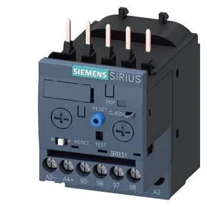
Siemens 3RB3113-4TB0 SIRIUS Overload Relay, 16 A
Siemens SIRIUS 3RB3113-4TB0 solid-state overload relay, Size S00, 16 A rated operational current, adjustable trip CLASS 5E/10E/20E/30E, screw terminals, contactor mounting.
Specifications
| Parameter | Value |
|---|---|
| Product brand name | SIRIUS |
| Product designation | solid-state overload relay |
| Frame size (overload relay) | S00 |
| Combinable contactor sizes | S00 |
| Reference code (IEC 81346-2) | F |
| Parameter | Value |
|---|---|
| Overload current setting range | 4 ... 16 A |
| Trip class | CLASS 5E, 10E, 20E and 30E adjustable |
| Overload release type | electronic |
| Parameter | Value |
|---|---|
| Rated operational current | 16 A |
| Poles (main circuit) | 3 |
| Rated operating frequency | 50 ... 60 Hz |
| Rated insulation voltage (AC, pollution degree 3) | 690 V |
| Rated value (AC-3e), max. | 690 V |
| Rated surge withstand voltage | 6 kV |
| Main current circuit | screw-type terminals |
| Power loss at rated current (hot) | 1.1 W |
| Per pole | 0.37 W |
| Parameter | Value |
|---|---|
| Auxiliary contacts: NO | 1 |
| Auxiliary contacts: NC | 1 |
| Auxiliary contacts: CO (changeover) | 0 |
| Auxiliary switch short-circuit protection (required fuse) | fuse gG: 6 A |
| Switching current at 24 V | 2 A |
| Switching current at 60 V | 0.55 A |
| Switching current at 110 V | 0.3 A |
| Switching current at 120 V | 4 A |
| Switching current at 125 V | 0.3 A |
| Switching current at 220 V | 0.11 A |
| Switching current at 230 V | 3 A |
| Parameter | Value |
|---|---|
| Mounting / fastening method | Contactor mounting |
| Mounting position | any |
| Main-circuit connector arrangement | Top and bottom |
| Auxiliary/control circuit connection type | screw-type terminals |
| Removable aux./control terminal | Yes |
| Conductor cross-section: solid | 1x (0.5 ... 4 mm²), 2x (0.5 ... 2.5 mm²) |
| Conductor cross-section: solid or stranded | 1x (0,5 ... 4 mm²), 2x (0,5 ... 2,5 mm²) |
| Conductor cross-section: finely stranded with ferrule | 1x (0.5 ... 2.5 mm²), 2x (0.5 ... 1.5 mm²) |
| Conductor range (AWG), auxiliary contacts | 1x (20 ... 14), 2x (20 ... 14) |
| Parameter | Value |
|---|---|
| Operating temperature | -25 ... +60 °C |
| Storage temperature | -40 ... +80 °C |
| Transport temperature | -40 ... +80 °C |
| Relative humidity, operating | 10 ... 95 % |
| Max. installation altitude | 2 000 m |
| Shock resistance | 15g / 11 ms |
| Parameter | Value |
|---|---|
| Width | 45 mm |
| Height | 79 mm |
| Depth | 73 mm |
Product details
Frequently asked questions
What does the 'for message tripped' note mean on this overload relay?
The note indicates that the auxiliary contact (terminals 97/98) is specifically designated as the 'tripped' signaling output. When the relay trips on overload, this contact changes state to indicate the fault condition. It's the output you wire to a PLC input, alarm light, or shutdown circuit to get a positive indication that the relay has operated.
Will the 3RB3113-4TB0 fit a panel designed for a 3RV1011-1HA10?
No, these are different form factors. The 3RB3113-4TB0 is a Size S00 solid-state overload relay designed for contactor mounting onto a Siemens S00 contactor. The 3RV1011-1HA10 is a motor starter protector (circuit breaker) with a different footprint and mounting method. They are not drop-in replacements without panel rework.
What compliance documentation does Siemens provide for the 3RB3113-4TB0?
The relay carries a substance prohibitance date of 10/01/2009, indicating RoHS compliance per EU directive. Standard Siemens documentation includes a CE declaration of conformity and a product certificate. For specific UL, IEC, or REACH documentation, request it with the RFQ — the manufacturer provides it with the shipment.
Active production — what that means for your BOM line
The 3RB3113-4TB0: It's a SIRIUS solid-state overload relay, Size S00, rated for a thermal current Ith of 16 A at up to 690 V. The solid-state design means no bimetal drift over time, so the trip curve stays consistent across the operating life — relevant for applications where nuisance tripping from thermal aging is a concern.
Trip class adjustability — setting the curve to the load
This relay offers four selectable trip classes: CLASS 5E, 10E, 20E, and 30E. That's the full range from fast-acting (5E, for pumps or compressors that lock rotor quickly) to slow (30E, for high-inertia loads like fans or centrifugals that need a longer start duration without tripping). The adjustment is on the device itself, so you can dial it in during commissioning without swapping hardware. The current setting range is defined by the motor current relative to the upper and lower setting values: the motor current must be greater than the lower setting value and less than the upper setting value multiplied by 3.5. That's a wide window — it means the relay can be set to protect motors with a full-load current anywhere within the adjustment range, with a 3.5× margin on the upper end for starting inrush.
Mounting and panel fit — contactor-mount, no DIN rail needed
Fastening method is contactor mounting — it clips directly onto the Siemens S00 contactor (e.g., 3RT201 or 3RT202 series). No DIN rail required, which saves a slot in a crowded panel. Dimensions: 45 mm wide, 79 mm high, 73 mm deep. Mounting position is any orientation, so no restrictions on vertical vs horizontal placement.
Environmental and compliance — shop floor and regulatory fit
Temperature compensation is built in over the same -25 to +60 °C range, so the trip curve doesn't shift with ambient changes — important for panels near ovens or in unconditioned spaces. Shock resistance is 15 g / 11 ms for the main relay, and 9 g / 11 ms for the signaling contact in the tripped position. Vibration resistance is 1–6 Hz at 15 mm amplitude, 6–500 Hz at 20 m/s², 10 cycles per axis. These ratings mean it holds up on a machine tool or conveyor line without nuisance trips from mechanical shock. Substance prohibitance date is 10/01/2009 — this is the RoHS compliance cutoff for the EU directive. The relay meets RoHS requirements for materials restrictions as of that date.
Auxiliary contact ratings — what the signaling circuit can handle
At 24 VDC, the 2 A rating is enough for most solid-state inputs; at 120 VAC, 4 A handles a contactor coil or indicator lamp directly. Power dissipation per pole is 0.37 W. For a three-pole relay that's about 1.1 W total — negligible heat contribution to the panel, so no derating needed in a standard enclosure.