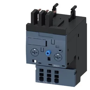
Siemens 3RB3113-4TE0 SIRIUS Solid-State Overload Relay, 16 A
Siemens SIRIUS 3RB3113-4TE0 solid-state overload relay, S00 frame size, 16 A thermal current, adjustable trip classes 5E/10E/20E/30E, 690 V rated, contactor-mount, spring-loaded terminals.
Specifications
| Parameter | Value |
|---|---|
| Product brand name | SIRIUS |
| Product designation | solid-state overload relay |
| Frame size (overload relay) | S00 |
| Combinable contactor sizes | S00 |
| Reference code (IEC 81346-2) | F |
| Parameter | Value |
|---|---|
| Overload current setting range | 4 ... 16 A |
| Trip class | CLASS 5E, 10E, 20E and 30E adjustable |
| Overload release type | electronic |
| Parameter | Value |
|---|---|
| Rated operational current | 16 A |
| Poles (main circuit) | 3 |
| Rated operating frequency | 50 ... 60 Hz |
| Rated insulation voltage (AC, pollution degree 3) | 690 V |
| Rated value (AC-3e), max. | 690 V |
| Rated surge withstand voltage | 6 kV |
| Main current circuit | spring-loaded terminals |
| Power loss at rated current (hot) | 1.1 W |
| Per pole | 0.37 W |
| Parameter | Value |
|---|---|
| Auxiliary contacts: NO | 1 |
| Auxiliary contacts: NC | 1 |
| Auxiliary contacts: CO (changeover) | 0 |
| Auxiliary switch short-circuit protection (required fuse) | fuse gG: 6 A |
| Switching current at 24 V | 2 A |
| Switching current at 60 V | 0.55 A |
| Switching current at 110 V | 0.3 A |
| Switching current at 120 V | 4 A |
| Switching current at 125 V | 0.3 A |
| Switching current at 220 V | 0.11 A |
| Switching current at 230 V | 3 A |
| Parameter | Value |
|---|---|
| Mounting / fastening method | Contactor mounting |
| Mounting position | any |
| Main-circuit connector arrangement | Top and bottom |
| Auxiliary/control circuit connection type | spring-loaded terminals |
| Removable aux./control terminal | Yes |
| Conductor cross-section: solid | 2x (0.25 ... 1.5 mm²) |
| Conductor cross-section: solid or stranded | 2x (0,25 ... 1,5 mm²) |
| Conductor cross-section: finely stranded with ferrule | 2x (0.25 ... 1.5 mm²) |
| Conductor range (AWG), auxiliary contacts | 1x (24 ... 16), 2x (24 ... 16) |
| Parameter | Value |
|---|---|
| Operating temperature | -25 ... +60 °C |
| Storage temperature | -40 ... +80 °C |
| Transport temperature | -40 ... +80 °C |
| Relative humidity, operating | 10 ... 95 % |
| Max. installation altitude | 2 000 m |
| Shock resistance | 15g / 11 ms |
| Parameter | Value |
|---|---|
| Width | 45 mm |
| Height | 72 mm |
| Depth | 90 mm |
Product details
Frequently asked questions
What does the 'for message tripped' note on the 3RB3113-4TE0 mean?
The note indicates the auxiliary contact set (terminals 97/98) is used to signal a tripped condition back to the control system. The signaling contact has its own shock rating — 9g / 11 ms in the tripped position versus 15g / 11 ms for the main contacts.
S00 Frame, 16 A Continuous — What Fits Where
The 3RB3113-4TE0 is a SIRIUS solid-state overload relay in the S00 frame size — 45 mm wide, 72 mm tall, 90 mm deep. It mounts directly onto a contactor (contactor mounting per), not on DIN rail, so the panel layout needs the contactor footprint first. Spring-loaded terminals on the main current circuit accept 2x 0.25...1.5 mm² solid or stranded wire. Rated thermal current Ith is 16 A at 690 V. The trip classes are adjustable — 5E, 10E, 20E, or 30E. That range lets you match the overload characteristic to the motor start profile: pump starts get 10E, high-inertia loads like fans or crushers get 20E or 30E. The solid-state sensing eliminates the bimetal drift you get with thermal relays — no ambient tracking issues across the -25 to +60 °C compensated range. The auxiliary contact set is rated 2 A at 24 V, 4 A at 120 V, 3 A at 230 V, and 0.55 A at 60 V. These are the switching limits for the trip signal back to the PLC or contactor coil — stay within them or buffer through an interposing relay.
Trip Classes and Motor Protection Logic
The relay trips when motor current exceeds the upper setting value by a factor of 3.5. The lower setting value is the minimum continuous current that keeps the relay reset. Between those boundaries, the selected trip class determines how long the relay holds before opening — 5E for fast-acting protection on short-start motors, 10E for standard IEC motor starts, 20E or 30E for high-inertia loads where start times exceed 10 seconds. Shock resistance is 15g / 11 ms on the main contacts; the signaling contact in the tripped position derates to 9g / 11 ms. Vibration resistance follows IEC 60068-2-27: 1-6 Hz at 15 mm amplitude, 6-500 Hz at 20 m/s², 10 cycles. That covers most rotating machinery environments — the relay is not the weak link in a motor starter on a pump skid or conveyor drive.
Active Production — Sourced to Order
Storage and transport temperature range is -40 to +80 °C. The relay carries a substance prohibitance date of 10/01/2009, which aligns with RoHS compliance — the exact RoHS/REACH declaration can be provided with the quote.