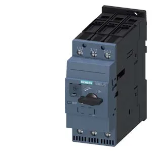
It is designed for motor protection, not general distribution, which means its trip curve is shaped to match induction motor inrush and thermal characteristics. This is the standard choice for most conveyor, pump, and fan applications. Ground fault detection is not included — that would require an external core-balance relay or a separate ground-fault module.
The interrupting ratings are given at multiple voltages, which matters for panel coordination. At 240 V it can clear 100 kA; at 400 V it handles 30 kA; at 500 V it drops to 4 kA; at 690 V it manages 2 kA. The 30 kA at 400 V is the figure most European panel builders will check first — it determines whether this breaker can be used without a current-limiting upstream fuse in a typical 400 V industrial supply with a 25 kA prospective fault level. Motor power ratings: 18.5 kW at 230 V, 25 hp at 220/230 V, 50 hp at 460/480 V. These are the AC-3 (squirrel-cage motor starting) ratings that govern the motor FLA it can protect.
The 55 mm width and 149 mm depth are the dimensions that matter for panel layout — it occupies a single 55 mm module on the rail. The side clearance of 10 mm is tight — adjacent devices can be butted close, but the 50 mm vertical clearance above and below is needed for arc-quenching and heat dissipation. Main circuit terminals accept 2× (1–35 mm²) or 1× (1–50 mm²) solid or stranded copper. Screw-type terminals with M6 thread.