Speed-torque envelope depends on supply voltage
The SH31402P02F1200: This motor delivers nominal speeds of 750 rpm on 115 V single-phase, 1500 rpm on 230 V single-phase, 3000 rpm on 400 V three-phase, and 3600 rpm on 480 V three-phase. The nominal torque drops as voltage rises — from 164.6 lbf.in (18.6 N.m) at 115 V single-phase down to 85.9 lbf.in (9.7 N.m) at 480 V three-phase — so the application voltage directly sets the available torque at rated speed. Continuous output power also shifts with the supply: 1460 W on 115 V single-phase, 2690 W on 230 V single-phase, 3860 W on 400 V three-phase, and 3660 W on 480 V three-phase. The 3900 W continuous power rating in the spec table corresponds to the three-phase 400 V operating point.
Peak vs continuous torque — the stall duty boundary
Peak stall torque is 531.9 lbf.in (60.1 N.m) across the 115–480 V three-phase range, but the continuous stall torque is limited to 172.6 lbf.in (19.5 N.m) over the same voltage window. That 3:1 ratio means the motor can deliver short bursts for acceleration or overload, but sustained stall or low-speed high-torque operation must stay below the continuous limit to avoid exceeding the 130 °C copper hot temperature ceiling. Natural convection cooling (no fan) means the thermal time constant is longer and the duty cycle in stalled or low-rpm conditions is the binding constraint — forced cooling would raise the continuous torque ceiling, but this motor relies on chassis radiation and airflow across the housing.
Encoder, brake, and environmental sealing
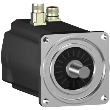
The absolute multiturn SinCos Hiperface encoder provides position feedback without a home cycle on power-up — useful for applications where the axis must retain its position reference through a power loss. The holding brake delivers 203.6 lbf.in (23 N.m) static torque, enough to hold a vertical load at rest without servo current. IP65 on the motor body and shaft bushing, IP67 on the housing per IEC 60034-5 — the shaft bushing seal is the weaker link in washdown environments; the housing itself handles brief submersion. The straight electrical connector mates without a right-angle adapter, which simplifies cable routing in tight cabinets.
Mounting dimensions and bearing load limits
The 140 mm (5.5 in) flange with an international standard pattern uses four 11 mm mounting holes on a 130 mm centring collar. The smooth 24 mm shaft extends 50 mm — no keyway, so the coupling must transmit torque through a clamping or friction fit. Maximum radial force at the shaft centre is 2240 N at 1000 rpm, derating to 1550 N at 3000 rpm; axial force is capped at 300 N. Exceed these and the bearing L10 life drops below the motor's service interval.
Electrical parameters for drive commissioning
Stator resistance is 0.6 Ohm and inductance is 3.855 mH — these set the electrical time constant and influence the current-loop tuning gains in the servo drive. The torque constant is 1.47 N.m/A at 120 °C copper temperature, and the back-EMF constant is 101 V/krpm at 20 °C. Maximum continuous current is 44.1 A RMS, which is also the 3-second peak current rating — the drive's current limit should be set at or below this value to protect the windings.