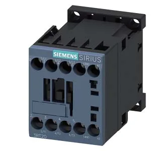
Its 45 mm width and 58 mm height (73 mm depth) let it fit into a standard 35 mm DIN-rail enclosure without crowding adjacent devices — the side clearance spec of 6 mm is the minimum to adjacent metalwork, so plan your gland-plate layout accordingly.
The headline switching-frequency ratings tell you how many operations per hour the contactor can sustain without exceeding its thermal limits: 1 000 cycles/h under AC-1 (resistive loads), 750 cycles/h under AC-2 and AC-3 (slip-ring and squirrel-cage motors), and 250 cycles/h under AC-4 (plugging/inching duty). The AC-3e rating matches the standard AC-3 figure at 750 cycles/h, so if you are driving a standard induction motor start/run cycle, that is the number to design against. For high-duty applications like frequent reversing or jogging, the AC-4 limit of 250 cycles/h governs — exceeding that rate will accumulate thermal stress in the arc chamber faster than the contactor can dissipate it. The auxiliary contact block (present on this variant) carries a 24 V rated current of 10 A, derating to 2 A at 48 V and 60 V, 1 A at 110 V, 0.9 A at 125 V, 0.3 A at 220 V, and 3 A at 400 V. Those are the make/break capacities for the control circuit — if your PLC output card sinks more than 10 A at 24 VDC, you need an interposing relay, not a direct drive from this auxiliary.
Wiring and mounting constraints
The main contact torque spec is 20 to 12 N·m.
Environmental and operating limits
The arcing time is 10 to 15 ms at 50/60 Hz with a power factor of 0.25 — that is the window during which the arc must be extinguished, and it is consistent with the AC-3/AC-4 ratings above. If your application involves frequent switching near the upper temperature limit, expect the arcing time to drift toward the higher end of that band.