What it does on the backplane
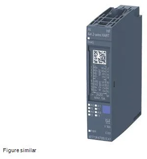
The Siemens 6ES7134-6TD00-0CA1 is a SIMATIC ET 200SP analog input module with 4 differential inputs, each on the 4 mA to 20 mA range resolved to 15 bit + sign. It is the 4-channel current-mode AI in the ET 200SP family — MSI is not supported on this variant, so the only usable measuring range is 4 mA to 20 mA. Channel status is shown on a green LED, and module diagnostics on a green/red DIAG LED. Measurement runs on the integrating (Sigma-Delta) principle. For an integrator that is the so-what behind good mains-frequency noise rejection in a plant panel, and the reason the per-channel cycle time is what it is rather than the faster successive-approximation figure seen on RTD/TC modules.
Loop power and field wiring
Sensor supply on the module delivers 20 mA continuous per channel, with a 50 mA peak allowed for under 10 s — that's the headroom you need for two-wire transmitters with a momentary inrush, but it is not a steady-state rating. Short-circuit protection is per channel, covering both encoder supply to ground and an input short to the encoder supply. Wire-break detection runs channel by channel, not group-wise. With 4-20 mA only, that is the right cut — you can alarm on a broken loop at the panel without losing the rest of the rack. The shielded cable length is rated to 800 m maximum. Past that, plan a signal conditioner or a repeater, not a different module.
Diagnostics the field tech will actually use
Per-channel diagnostics cover wire-break, short-circuit, overflow/underflow, and a hardware limit value alarm — all reported individually, with a group-error summary in parallel. A separate diagnostic alarm raises a process interrupt on the head station. On the housing, channel faults light the red per-channel LED, module status lights the green/red DIAG LED, and a green channel-status LED shows healthy operation. No inter-channel isolation is provided, and the 4-20 mA inputs share a common ground reference. Loop-powered transmitters in the same field segment must therefore respect that common-mode limit, which the 707 V DC type-tested isolation to the backplane is built to absorb.
BaseUnit, power, and version slot
The module snaps into BU type A0 or A1 base units. It runs on a rated 24 V DC supply, draws 0.65 W typical dissipation with no sensor connected, and firmware is field-updatable — the as-shipped version is V1.0. I&M0 to I&M3 data is supported, so the asset record and the installed-location tag survive a head-station swap. Automatic encoding is on, so the head will recognize the slot on power-up without a manual slot reconfiguration step.